

Improving Coverage for ECU Outliers
Variables include the number of outputs tested at one time and spikes in output.
Conventional automotive electrical test methods only test each output from the electronics one by one and sequentially. This leaves a gap in the test coverage where faults, or outliers that occur simultaneously due to unexpected outputs from the electronics, are not tested or checked.
Let’s look at how to address this gap to ensure ECU outliers are covered. Automobiles these days are virtually moving computer systems, embedded with many electronic control units. As the brains of the automobile, ECUs control everything from the fuel or ignition timing to security or lights. For occupant safety, the function of all ECUs in the motor vehicle must be at tip-top condition. This means that every single control signal and data passing between the ECUs and other electronics or mechanical parts on the car must be as expected and without any uncertainty.
During ECU manufacturing, all input and output (I/O) signals from each unit are tested to ensure that they function as required by their specifications. Take the example of a Body Control Module that controls the headlights. Different signals are output from the BCM to control different settings of the headlights, such as high or low beam, left or right lights, fog lights, etc. The conventional test method tests each output individually to ensure the lights are turned ON and OFF correctly.
Conventional test methods. What happens if both the high beam and low beam signals are output from the ECU when only the low beam signal is switched on? The conventional test method, by testing only one output at a time (either the high or low beam output but not both), will not be able to catch this fault.
Let’s take the example of the headlight BCM, where the aim is to test the different functionalities of the headlight, such as the high or low beams and fog light. An input to each function is switched on so that the corresponding output is observed. For instance, when testing the low beam setting, the output signal for the low beam is checked to see if it is in the ON or OFF state, but the other outputs, high beam or fog lights, are not checked or monitored. Subsequently, when testing the high beam setting, the output signal for the high beam is checked to ensure that it is functioning correctly in the ON or OFF state, but the output signals of the low beam or fog lights are not monitored.
In the test, a switching matrix is used to channel the signals to one digital multimeter (DMM) in the test system. One DMM can do one measurement at a time. So, only one output can be tested at a time, after which the next output will be switched to the DMM for testing and so on. This method of testing assumes that no two signals will be output simultaneously, if only one setting is set. To rectify this situation, all the different outputs need to be tested for each setting. Since the current methods require that each output be measured one by one, the cumulative test time for testing each setting multiplies by the number of outputs tested, resulting in a high overall increase in test time (Figure 1).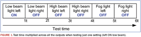
Different possible fault scenarios. Different fault scenarios can occur in the actual production environment, with one test setting demonstrating multiple types of output. For instance, in a case study where the setting was to test the left low beam light under both ON and OFF conditions when the input signal was toggled, multiple “abnormal” output scenarios were observed with the left high beam light (Figure 2).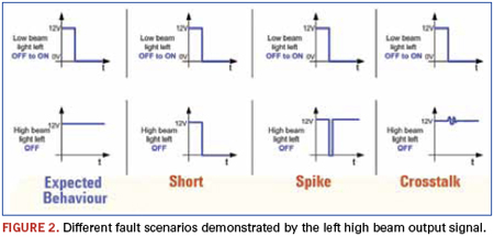
In the case of a spike in the output of the “high beam light left” when the “low beam light left” was toggled, conventional test methods may not capture this spike using the DMM because the resolution of the DMM may not be adequate enough to capture the small pulse width of the spike. If this spike was exhibited in the engine timing circuit, it could cause massive damage to the engine block due to the stress of the pistons being triggered out of time. In the crosstalk scenario, where there is crosstalk between the left low beam light and the left high beam light outputs, this could be a result of the reduction in size of today’s ECUs such that the adjacent outputs are very close in proximity to each other.
With the complexity in today’s ECUs, if outlier faults like such a crosstalk were to occur from a headlight with the affected output signal being that for the airbag control, it could erroneously activate the airbag, causing injury to the passenger. Note that the crosstalk cannot be detected by the DMM correctly.
Parallel measurement is another method of closing the gap and maintaining the original test time. However, to accomplish this, multiple DMMs need to be configured into the test so that they can be triggered to take the measurements in parallel. The cost would be a multiple of the number of outputs to be tested in parallel, which would result in a large increase in the overall test system cost. This is also a reason why this method is not popular.
Multiple-channel voltage acquisition can enable faster parallel test. A data acquisition unit is a good choice, as it has multiple analog input ports to measure multiple channels at one time.
As mentioned above, while the main example described testing a car’s headlight system, the possibility of similar test coverage gaps can occur during the testing of other ECUs in the automobile. These include airbag control, anti-lock braking control, powertrain control or engine control. Increasingly, along with technology advancements, we are seeing one ECU perform multiple functions. It is thus necessary to determine not only that the ECU exhibits the correct outputs according to the related input, but, at the same time, that all other outputs are also behaving correctly. Only then are we able to guarantee the automobile can function correctly, as expected, and the safety of the occupants is preserved.
Cynthia Chuah is technical marketing engineer at Agilent Technologies (agilent.com); cynthia_chuah@agilent.com.


