

Assembling Rigid-Flex Panels

Making the switch from rigid means new profiles and fixturing.
Question: Can flex and rigid-flex circuits be processed through assembly the same way as rigid PCBs?
Answer: The general assembly process is the same.Flex, rigid-flex and rigid PCBs all require solder paste application followed by component placement and reflow. But there are quite a few nuances unique to flex and rigid-flex processing, and these extra requirements can make the process very troublesome if they are not included in your process flow. I will go over each of these differences individually.
Solder paste application. Solder paste is applied to flex and rigid-flex printed circuit boards using a stencil and a screen printing operation, just like rigid PCBs. Where most assemblers stumble is the flimsiness and dimensional instability of the flexible circuit assembly panel. Unlike rigid PCB panels, flex panels many times will not lie flat and need to be anchored to the screen printing surface with pins or other fixturing. Moreover, flexible circuit materials are not dimensionally stable and can stretch or shrink up to 0.001" per inch just from temperature and humidity. And to make things more interesting, these stretch and shrink factors are usually not uniform across the x and y axes. For this reason, flex assemblies generally need smaller panels than those for rigid PCBs.
SMT component placement. As mentioned, flex circuit panels can grow and shrink a considerable degree with temperature, humidity and processing. With today’s tiny SMT components, being off even a little during component placement can cause issues during reflow. If the flex circuits are small, the stretch and shrink might not be a significant issue and accounted for with smaller zones within the SMT panel or additional fiducials for each smaller zone, or even separate fiducials for each part.
The lack of overall flatness of a flex panel can also throw a wrench into pick-and-place. SMT fixtures are more or less mandatory for this operation to keep the SMT surface flat and planar (FIGURE 1).
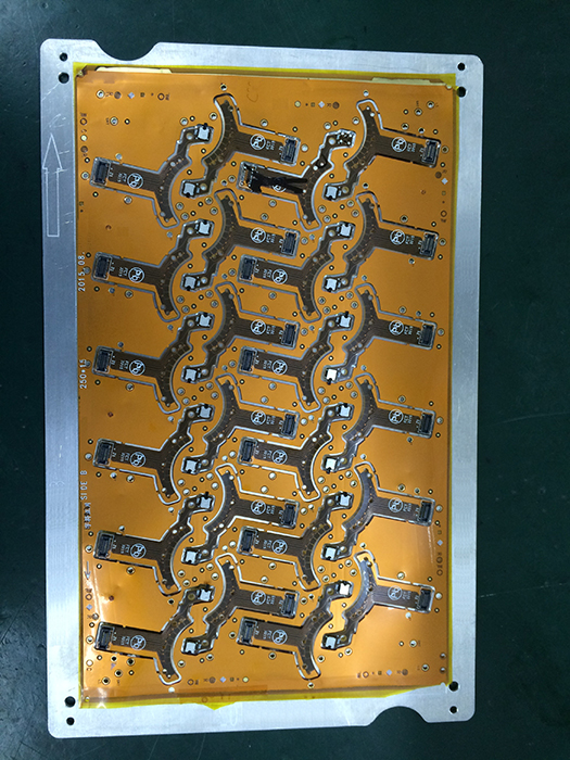
Figure 1. SMT fixtures require tooling to keep the flex panel flat during SMT processing.
Reflow. Prior to reflow, flex circuits must be dry, dry, dry. This may well be the single most important difference between flex and rigid PCB component assembly processing. In addition to flex materials being very dimensionally unstable, they are also very hygroscopic. They absorb moisture like a sponge (up to 3% by weight). Once a flex circuit has absorbed moisture, it is reluctant to give it up … until run through a reflow oven. At that point, the moisture release is so fast that the result is catastrophic delamination and blistering. Rigid PCBs can have similar issues with moisture, but overall seem much more tolerant. Prior to reflow, flexible circuits require a thorough pre-bake at ~225° to 250°F. This prebake should be done immediately (less than 1 hr.) prior to reflow. If the flex circuits cannot be reflowed immediately after prebaking, they must be stored in a dry box or nitrogen cabinet until they can be processed. If the parts are not processed within 24 hr. after prebaking, I recommend baking the parts again, even if stored in a dry environment. I have never seen a flex circuit explode during reflow because it was too dry, but I cannot say the same of ones that were not completely dry!
The required duration of a prebake cycle depends on the overall circuit thickness. The thicker the circuit, the longer it will take to drive out moisture. For standard thin flex circuits that are four layers or less, a 1 hr. prebake is usually sufficient. For thicker flex and rigid-flex, the prebake cycle should be extended to 2-plus hours. If you are not sure the bake cycle is long enough, run one panel through the reflow oven after prebaking but before starting SMT assembly. If the panel comes out of reflow looking good, start the SMT process. If there is blistering or delamination (which should be obvious with visual inspection under a scope at 10X), increase bake time.
Be sure to adjust the reflow profile for flex circuits. Remember, flex circuits have considerably less mass than rigid PCBs and therefore heat very quickly. Also, the flexible adhesives used to bond circuits together are not nearly as tolerant to high temperatures as is FR-4 or polyimide prepreg. Both time and temperature need to be lowered to get good overall reflow without damaging the flex circuit. The amount of adjustment to the reflow profile is driven by the overall circuit thickness.
Flex circuits that are only a couple layers will be very thin and will need to move through reflow very quickly. High-layer-count rigid-flex circuits are thicker and require reflow profiles closer to those of rigid PCBs. The best reflow profile is the one that works while limiting exposure to high temps.
is senior application engineer at Flexible Circuit Technologies (flexiblecircuit.com); mark.finstad@flexiblecircuit.com. He and co-“Flexperts” (mverbrugge@amphenol-afc.net) and (nick.koop@ttmtech.com) welcome your suggestions.


