

Addressing Low-Temperature Rework Concerns
Material properties and considerations of a eutectic SnBi solid wire and SAC 305 flux cored wire.
Low-temperature (LT), high-bismuth solders are being carefully considered to replace SAC 305 for several reasons, including minimizing component warpage, reducing energy consumption and lowering the cost of solder, substrate, plastics, and other materials. Bismuth is strong but brittle, and has different mechanical properties than the SAC alloys they are targeted to replace.1 Despite these drawbacks, consumer electronics not subjected to high thermal or mechanical stress may be candidates for low-temperature materials.
Most published studies have overlooked one important consideration when implementing low-temperature alloys: rework and post-assembly attachment processes. This article reviews issues associated with using low-temperature alloys in the benchtop setting and how these alloys can be implemented or combined with existing processes and materials.
SAC 305 is the PCB assembly standard solder since lead was banned from many electronic solders for environmental concerns in 2006. This change forced the implementation of new equipment and materials due to the higher melting temperature of SAC 305 versus the SnPb materials it replaced. One of the main benefits of SAC 305 is its compatibility with SnPb solders. Other elements considered for SnPb solder replacement were indium and bismuth, among others. Both were attractive as they lower the melting temperature of SAC alloys. However, indium was eliminated for supply and cost issues and bismuth was eliminated because when combined with SnPb, a ternary alloy with a melting temperature of 97˚C is formed, causing an unacceptable loss of reliability.
Regulations limiting use of Pb in electronics have effectively removed it from most of the industry’s material supply chain, reinvigorating the interest in Bi-bearing solder alloys. Given the advantages of a low-melting point alloy, solder manufacturers are motivated to develop commercially viable products for solder paste, solid alloy and flux-cored wire, but this is not without its challenges.
The physical properties of elemental bismuth are unusual. It has one of lowest thermal and electrical conductivity values of all metals, it is denser as a liquid than a solid, it expands on freezing, and is the most naturally diamagnetic element on the periodic table. Aside from these interesting factors, bismuth’s brittleness is what has the greatest impact on its soldering performance. An alloy with a bismuth percentage above 6% will begin to lose ductility and become more brittle. Brittleness should not be confused with loss of strength; bismuth alloys are strong, but brittle.
Sn42Bi57Ag1 is eutectic at 138˚C, meaning the liquidus to solidus are coincidental, there is no plastic/pasty state. Adding elements such as silver and indium can improve strength or ductility to high-bismuth alloys, but they will still behave like high-bismuth alloys – strong and brittle. This creates issues for PCB assemblers and has a profound impact on the manufacturability of SnBi wire solders. Manufacturing wire solder relies on the ductility of the alloy to permit it to be shaped and formed. When producing flux-cored wire, these traits are vital. Flux-cored wire is simply a metal tube formed around a die via an extrusion process, subsequently drawn through progressively finer dies. This thin metal tube is prone to cracking and breaking as the equipment relies on a continuous wire to operate correctly. Extrusion presses must be specially outfitted to run high-bismuth wires and run at significantly slower speeds compared to typical SAC alloys. These factors add considerable cost to manufacturing.
SnBi can recrystallize at room temperature. Therefore, this once-ductile material can become brittle over time, resulting in flux-cored wire solder being prone to breaking as it is unspooled. This makes low-temperature alloys poorly suited for fine-wire diameters or robotic soldering applications.
Finally, SnBi alloys are slower to wet compared to SAC, and therefore require more aggressive fluxes to promote spread and flow to facilitate barrel fill and sufficient wetting.2 These realities leave assemblers using low-temperature solders with three practical options when reworking assemblies: implement high-bismuth, low-temperature flux-cored wire solder with the material; implement solid high-bismuth wire solder with an external flux; or use SAC flux-cored wire in combination with the low-temperature alloy used during the assembly process.
The study evaluated these three options, provides feedback on performance characteristics during processing, and compares the resulting solder joints using IPC-A-610, cross-section evaluation and shear strength testing.
Experimental Methodology
Three rework conditions were followed to compare the performance of high-Bi solders to a SAC 305 baseline during rework and post-assembly processes. Condition 1 uses Sn42Bi57Ag1 paste and SAC 305 flux-cored wire. Condition 2 uses Sn42Bi57Ag1 paste but is different from condition 1 in that solid Sn42Bi57Ag1 wire and external flux is used. Finally, condition 3 employs SAC 305 paste and SAC 305 flux-cored wire for rework. All flux mediums in use are no-clean, thus cleaning was not performed.
The study used PC016 J-STD-001 REV F/G-LF Solder Training Kit (FIGURE 1) because of its combination of SMT and PTH component types. The surface finish was ENIG (electroless nickel immersion gold) with thicknesses of about 2[U]in gold and 120[U]in nickel, respectively. The assortment of components enables use of a combination of post-assembly soldering techniques. The following components were tested in this study.
- Cross-section: R1, U1, and CR3
- Shear testing: R3, R4, C3, C4, CR3, CR4, R5, and R6.
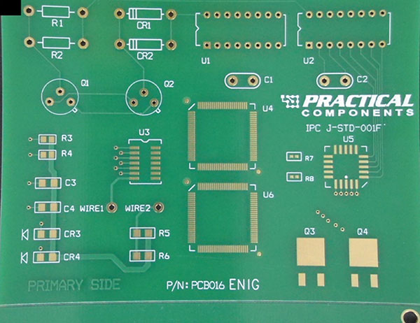
Figure 1. PC016-IPC J-STD-001-REV F/G-LF Solder Training Kit.
Phase 1 assembly took place in the company Solder Technical Applications laboratory in Juarez, Mexico. A 5-mil, laser-cut stencil using PHD stainless steel, mounted at standard tension (~34N/cm) with apertures designed to promote defects was employed. The stencil design included engineered defects such as BTC apertures combined into one to form solder bridging pads, indicated by the blue arrows in FIGURE 2. Also, one of each chip component outlined in red, per Figure 2, was printed using the inverted home-plate design while the second identical component was printed 1:1 with the pad to promote solder balling.
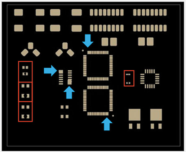
Figure 2. Stencil designed to promote defects.
The pin-in-paste (PiP) method was used for PTH components. Deposits were inspected for consistent paste volume using a Parmi SigmaX SPI. After printing, the board was populated using an I-Pulse M10 pick-and-place machine and PTH components were inserted manually. Boards were then soldered with their respective profiles using a Heller model 1936 MK5 convection reflow oven. A total of 18 boards were assembled to permit experimentation and assessment of various rework techniques. Twelve boards, listed in TABLE 1, were assembled with the company no-clean Sn42Bi57Ag1 paste following the reflow profile in FIGURE 3 with a peak temperature of 170˚C.
Table 1. Materials and Peak Reflow Temperatures Used for Low-Temperature Solder Assemblies
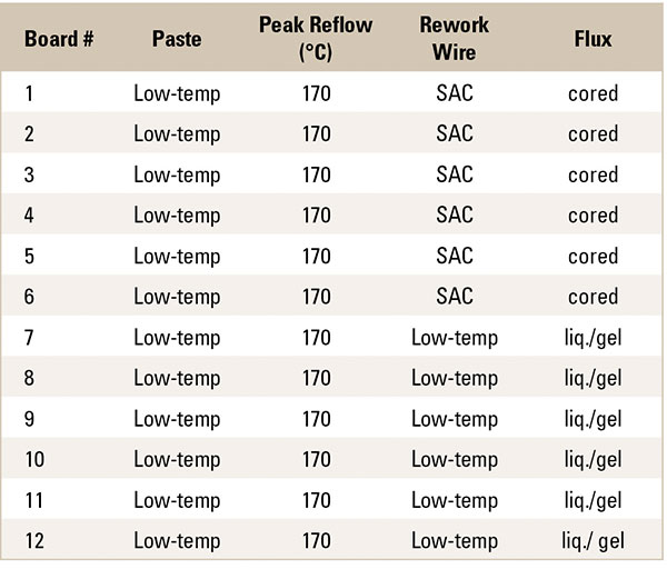
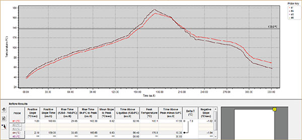
Figure 3. 170°C SnBiAg peak reflow profile.
Solder paste was printed using a DEK HORIZON 3AA.
Six boards, listed in TABLE 2, were assembled using the company no-clean SAC 305 paste following the reflow profile in FIGURE 4 with a peak reflow temperature of 246˚C.
Table 2. Materials and Peak Reflow Temperatures Used for SAC Solder Assemblies
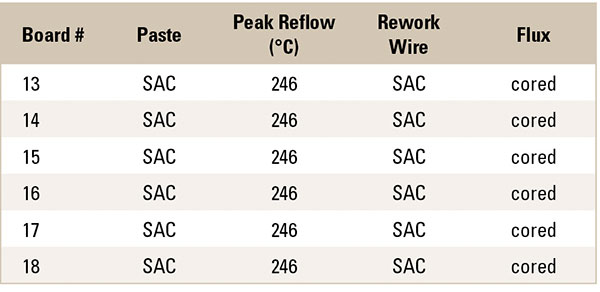
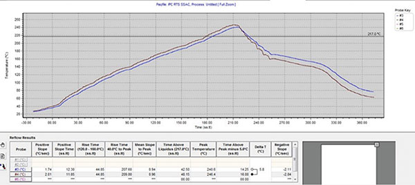
Figure 4. 246°C SnAgCu Peak reflow profile.
After assembly, the next phase was simulating various rework/post-assembly processing techniques under each soldering condition. This was conducted at Eptac Corp. Rework was performed with a soldering iron with a chisel tip set to 630˚F/330˚C (FIGURE 5). The company no-clean flux-cored SAC 305 wire was used to rework 12 total boards: six of the 12 assemblies using Sn42Bi57Ag1 paste, per condition 1, and six assemblies using SAC 305 paste, per condition 3. The remaining six boards assembled using Sn42Bi57Ag1 paste were reworked using solid Sn42Bi57Ag1 wire combined with the company no-clean liquid flux for PTH components and the company no-clean gel flux for SMT components, per condition 2.
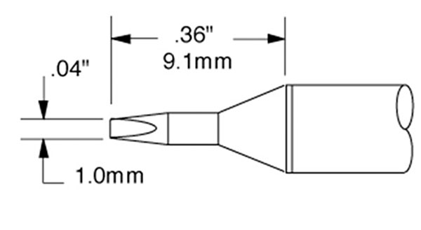
Figure 5. Chisel tip.
The second part of this phase comprised reproducing the rework techniques applied and capturing them on video.
Rework Techniques and Tooling
None of the components used in rework was prepped or pretinned prior to being assembled to the board.
PTH components were removed by cutting the component leads, applying liquid flux to the remaining solder joints, and removing the components with heated tweezers. Through-hole vias were cleaned with copper braid. Four axial components, two radial caps and one IC were removed from each board.
Surface-mount components were removed with heated tweezers. Pads were prepped for new components by applying no-clean liquid flux and solder braid to remove excess solder. No-clean rework gel flux was then applied, and a small amount of SnBi solder was applied to prepare for the installation of new components.
Once the pad terminations were prepared and fluxed, components were placed on the pads, the solder was reflowed using hot air, and the components were slid onto the molten solder alloy. The process was repeated on the opposite side.
Intentionally designed SMT defects, such as bridges on the gullwing components, were reworked by applying gel flux and copper braid, and heated with the soldering iron to wick the solder away. The joints were refluxed with the no-clean gel and the low-melt alloy was reapplied to verify the joint met the requirements of J-STD-001.
Analysis Methodology
Cross-section analysis was conducted on one PTH and two SMT components per soldering condition: R1, U1 and CR4, respectively. This was done to investigate the impact of the various rework techniques and soldering conditions on intermetallic compound (IMC) formation. Mechanical shear testing was conducted on SMT components R3, R4, C3, C4, CR3, CR4, R5, and R6 at a constant speed of 0.1mm/s and a shear height of 0.15mm.
Results
Rework observations. All surface-mount components were prepared using no-clean gel flux and PTH components with no-clean liquid flux. Solid low-temperature solder did not wet the solder iron tip as well as the flux-cored SAC 305 wire, which was unsurprising.
The solid SnBi wire worked well with the addition of the application of external flux. Solder joints were visually inspected and met the requirements of IPC/J-STD-001. When using solid low-temperature wire, the solder iron tip remained tinned and functional, with no degradation of the tip tinning.
When using SAC 305 flux-cored wire, soldering the smaller-size surface-mount components proved challenging due to the large wire diameter. Although the joints appeared to have excess solder, they met the wetting requirements according to J-STD-001.
Solder joint analysis cross-section analysis. Cross-section analysis showed typical IMC formation for all the reworked joints. FIGURES 6 to 13 display the typical IMC formation per each soldering condition. Figures 6 to 9 display PTH component, R1, while Figures 10 to 13 display SMT component CR4.
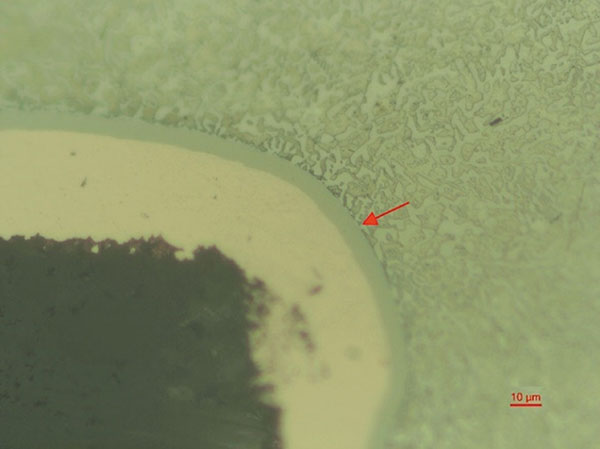
Figure 6. R1 PTH component assembled with Sn42Bi57Ag1 paste and reworked with solid Sn42Bi57Ag1 wire and external flux.
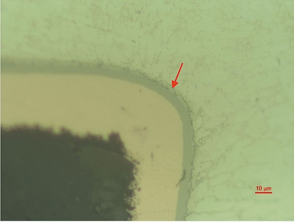
Figure 7. R1 PTH component assembled with Sn42Bi57Ag1 paste and reworked with SAC flux-cored wire.
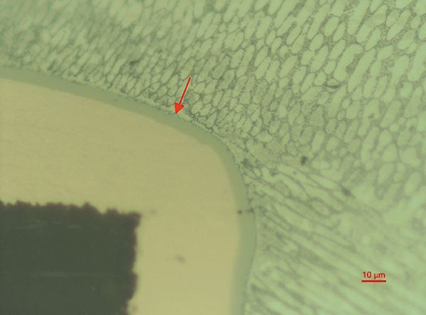
Figure 8. R1 PTH component assembled with SAC paste and reworked with SAC flux-cored wire.
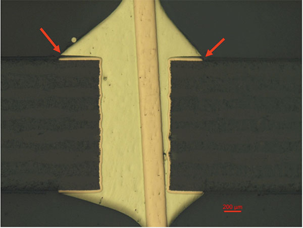
Figure 9. Fillet lift on U1 PTH component assembled with Sn42Bi57Ag1 paste and reworked with SAC flux-cored wire.
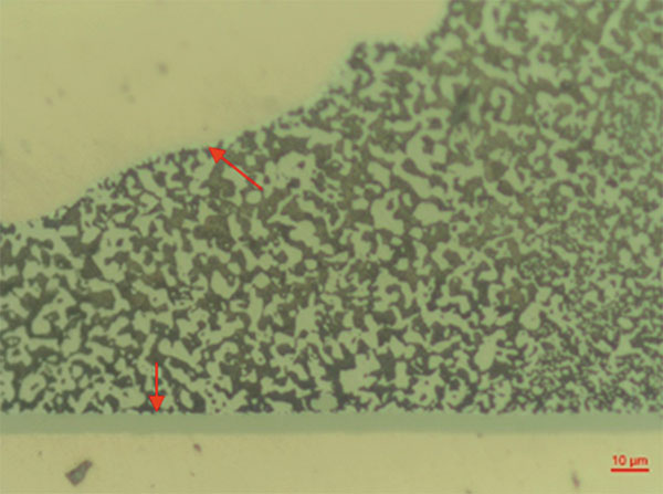
Figure 10. CR4 component assembled with Sn42Bi57Ag1 paste and reworked with solid Sn42Bi57Ag1 wire and external flux.
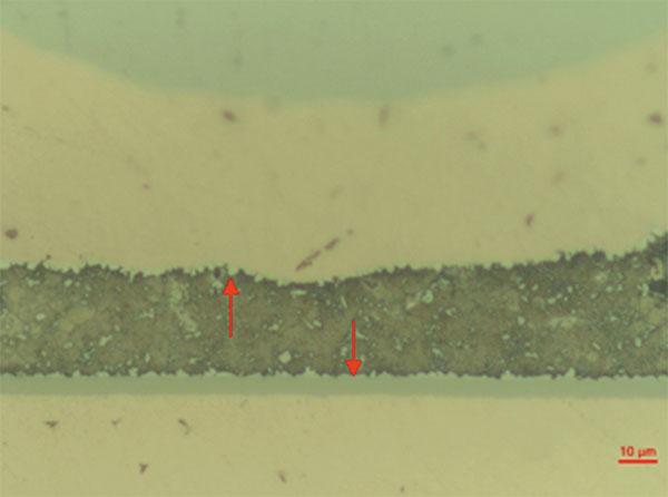
Figure 11. CR4 component assembled with Sn42Bi57Ag1 paste and reworked with SAC flux-cored wire.
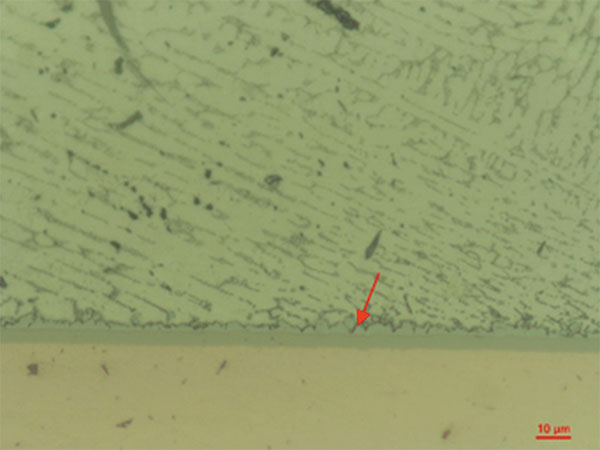
Figure 12. CR4 component assembled with SAC paste and reworked with SAC flux-cored wire, pad side.
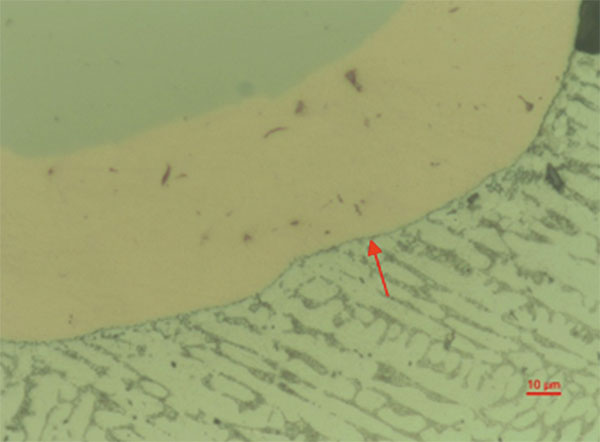
Figure 13. CR4 component assembled with SAC paste and reworked with SAC flux-cored wire, component side.
Almost all the PTH joints have 100%-barrel fill; however, the fillet-lifting phenomena on the topside were observed at R1 of board #2 and U1 of board #1 (Figure 8). Fillet lift is a common occurrence when using high-bismuth alloys and is not a defect per IPC-A-610.
On the SMT components, each IMC is well-formed, showing good wetting on the pads of the PCB and terminations of components. Figures 10 to 13 display the IMC formation per soldering condition on SMT component CR4.
In conclusion, rework has been successfully performed, with no observed defects under all test conditions. All solder joints were acceptable per IPC-A-610 inspection criteria.
Shear testing. Shear test results for components C3/C4, CR3/CR4, R3/R4, and R5/R6 are shown in FIGURES 14 to 17.
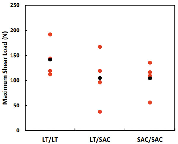
Figure 14. Shear force for C3/C4 components for the three test cells (red = each test, black = average).
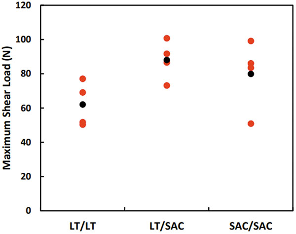
Figure 15. Shear force versus extension relationship for CR3 and CR4 components.
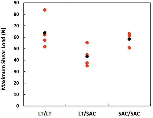
Figure 16. Shear force for R3/ R4 components for the three test cells (red = each test, black = average).
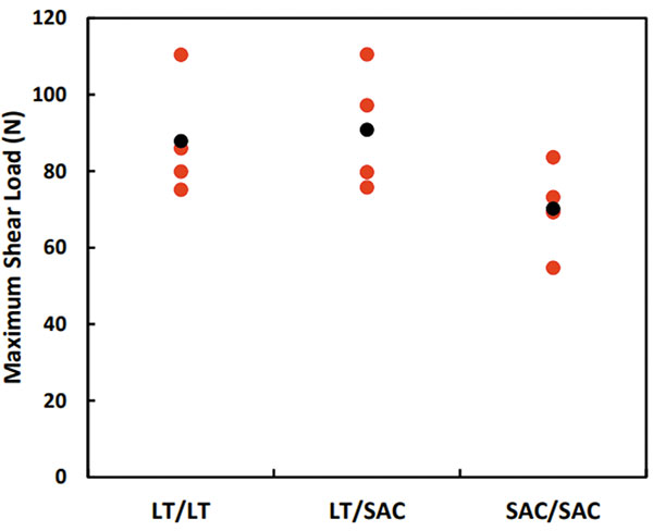
Figure 17. Shear force for R5/ R6 components for the three test cells (red = each test, black = average).
Each soldering condition performed comparably during shear testing per component type. The variation seen within a single soldering condition, no matter the component, is attributable to the variable nature of rework. Rework is a manual operation, and the quality of a reworked solder joint is highly influenced by operator input. Even the most expert operator producing acceptable solder joints will have variation in their work. Shear testing did not show a clear outlier in mechanical performance over the three soldering conditions. The low shear force values in Figure 13 can be attributed to inconsistent volumes of solder being applied to the joint, which is a result of the manual operation of rework.
FIGURES 18 to 20 display the typical shape seen in a shear force versus extension relationship for each soldering condition/test cell. The results of component R5 are shown in the following figures. The high-bismuth (LT reworked with LT) curve seen in Figure 18 is sharp, indicating that the alloy can withstand load (N) but breaks abruptly due to its brittle properties.
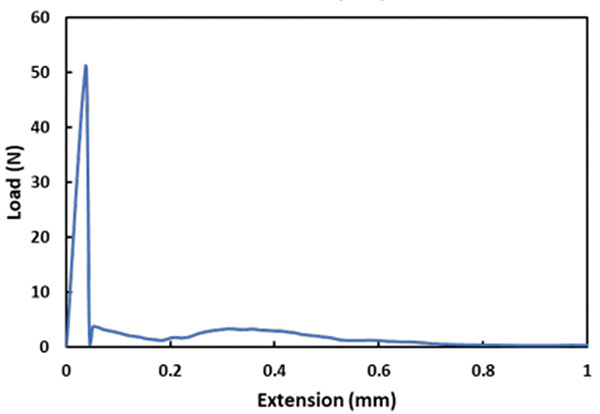
Figure 18. Typical shear force versus extension relationship for component printed with LT paste and reworked with LT wire and external flux (R5).
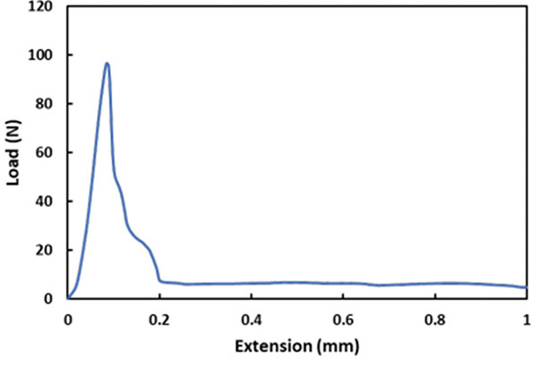
Figure 19. Typical shear force versus extension relationship for component printed with LT paste and reworked with SAC flux-cored wire (R5).
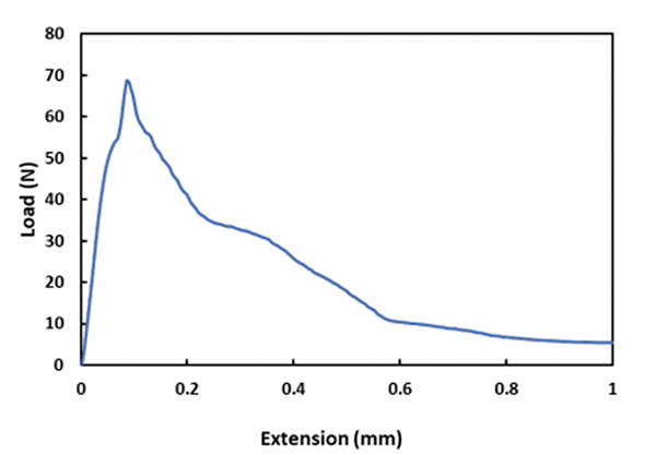
Figure 20. Typical shear force versus extension relationship for component printed with SAC paste and reworked with SAC flux-cored wire (R5).
Figure 19 shows the curve of the LT paste reworked with SAC flux-cored wire, displaying a less sharp curve and greater extension (mm), indicating it is more ductile than the LT paste reworked with LT wire and external flux (Figure 18).
Finally, Figure 20 illustrates how the SAC paste reworked with SAC flux-cored wire extends the greatest but withstands less load (N) before extension compared to the LT paste reworked with SAC flux-cored wire (Figure 19).
Conclusions
Low-temperature alloys used in SMT and PTH processes can be successfully reworked using low-melting temperature solid wire and external flux as well as with flux-cored SAC 305 wire solder. Low-temperature solder behaves differently during processing than the SAC equivalent, but this was not an obstacle in creating quality solder joints. LTS solid wire with external flux will require qualification of an appropriate flux for the application requirements. As with any externally applied flux, residue and reliability characteristics due to processing techniques must be considered.
The resulting solder joints met IPC Class 1, 2 and 3 solder joint criteria. Shear test results were inconsistent due to the variable nature of rework, but trends are visible. SAC solder joints were more ductile than Bi-bearing counterparts. This is not unexpected. SAC+SnBi solder joints shear results reflected the properties of the combined alloys. The operator in this study was an IPC hand soldering certification instructor with decades of experience. Even with a highly qualified operator, results are variable. This highlights the importance of operator training in implementation of low-temperature rework.
When using SAC 305 flux-cored wire solder, the process was like existing SAC/SAC rework processes. No special considerations were noted other than to consider the use of finer wire diameters when reworking smaller components.
Low-temperature flux-cored wire solder was not included in this study due to the prohibitive cost to the end-user and limited availability.
Future Work
Based on the outcomes of this study, more testing has been scheduled. The effect of low-temperature alloys on soldering iron tip life and equipment will be evaluated. In theory, lower operating tip temperature will extend solder tip life, offering another cost-saving opportunity for low-temperature implementation. In addition, low-temperature alloy flux residue was noticeably darker than SAC alloy residue. Analysis indicated the presence of bismuth oxide, which is an aesthetic concern. Future testing will include the ease of cleaning these dark residues in both the assembly and rework setting.
Acknowledgments
The authors would like to thank the Applications Lab Team at AIM, Andres Lozoya, Angel Lopez and Ruben Sanchez, for their patience and dedication. We would also like to acknowledge the input and guidance of Yuan Xu of the AIM metallurgy department, whose knowledge helped make this study possible.
References
- D. Witkin, “Influence of Microstructure on Mechanical Behavior of Bi-Containing Pb-Free Solders,” IPC Apex Expo, 2013.
- H. Osgood, D. Geiger, R. Pennings, C. Biederman, J. Jiang, J. Bernal, “Low-Temperature SMT Solder Evaluation,” IPC Apex Expo, 2019.
Ed.: This article is adapted from a paper published at SMTA International in November 2022 and is reprinted here with permission of the authors.
and are with AIM Solder; toneill@aimsolder.com. is with Eptac Corp.; leo@eptac.com. is an independent consultant; bob@bobwillisco.uk. , Ph. D. is at Auburn University; smh0083@auburn.edu.


Press Releases
- Altus Group Invests in Major Headquarters Expansion to Showcase Complete Turnkey Manufacturing Capability
- ViTrox Americas Welcomes Eric Cruz as Technical Support Engineer
- ECD Strengthens Engineering Team with New Software Development Hire
- ViTrox Americas Welcomes Doug Ennis as Senior Field Applications & Service Engineer