

Operation of a Vacuum Reflow Oven with Preliminary Void Reduction Data
MLF trials show relatively soft vacuum levels and short hold times can significantly lower voiding.
Vacuum reflow has been around for some time with only slight interest but is now gaining attention in electronics assembly because of a desire to lower and even eliminate voids in solder joints and thermal pads.
Initially, vacuum reflow was a batch operation in which boards were placed in a vacuum chamber and heated to melt the solder. During the heating process the chamber was evacuated and the void level was reduced or, in some cases, removed from the solder joint. Sometimes the vacuum was applied when solder approached liquidus, and at other times vacuum was applied during the entire heating cycle. The equipment was expensive to purchase and operate, but the biggest detriment was throughput. Therefore, vacuum reflow was not appropriate for high-volume production. Additionally, there were questions about the need to eliminate voids, with some claiming a small number of voids in joints actually increases their apparent strength.
There was little motivation to pursue vacuum reflow until the need to dissipate heat from high-power components came on the scene, especially automotive under-the-hood components. At first, vias seemed part of the answer, but it was impossible to guarantee a via would be under the “hot spot” in the component. Therefore, low or no voids in the thermal pads seems the answer.
Today “low voids” can mean anything from 20% to zero. Numerous engineers say 5% is the desired realistic limit. The question became how do we get from the current 40%+ voids in thermal pads to 20% and below with high-volume production equipment? Solder paste and thermal profile modifications have helped, but void levels consistently below 5% are a stretch.
The answer is a continuous vacuum-assisted reflow oven, in which a vacuum chamber is placed between the last heated zone and the cooler in a standard convection reflow oven. This presents material and engineering design challenges because the board must be transported in and out of the chamber. the vacuum section must seal, and vacuum must be applied – all at elevated temperatures. Numerous designs currently used for the internal vacuum chamber employ entrance and exit doors or bell jar configurations (FIGURE 1). Doors tend to be lightweight and move easily, while the bell jar design makes access to the conveyor system inside the chamber simple. The transport system presents issues because the edge rails must be interrupted for the door or bell to seal, and the board must stop in the chamber while the vacuum is applied. In each case the seal material must withstand temperatures approaching 350°C.
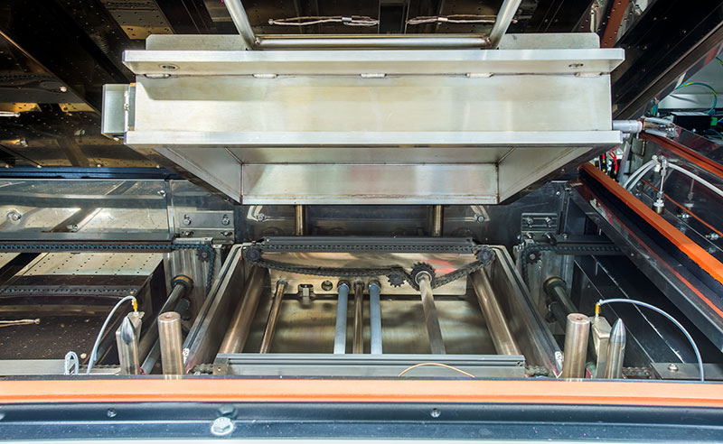
Figure 1. Bell jar design vacuum chamber.
This brings us to the process steps encountered in a continuous vacuum reflow system. Initial heating is exactly like a normal reflow oven, where convection rate, zone set points and belt speed are the control factors in heating the board. Once the board begins to enter the vacuum chamber, we forgo the power of convection to heat the board and need to rely on radiation for continued heating. Once the board is in the vacuum chamber, four things need to be controlled: pump down rate, vacuum level, vacuum hold time, and equalization rate.
Pump down rate: The speed at which the vacuum is applied. If too fast, voids can explode as they leave the joint or pad and produce solder balls or splatter. If too slow, time is wasted and time above liquidus (TAL) extended.
Vacuum level: The amount of vacuum the board is exposed to. Levels as low as 1 Torr and as high as 250 Torr (and higher) are possible. Even with a very large vacuum pump, it takes longer to go to low vacuum levels.
Vacuum hold time: The time the board is exposed to the vacuum selected. Hold times can be as short as 1 sec. or as long as a few minutes. At 1 sec. there is little time for the voids to exit. Hold times greater than 40 sec. have proven unnecessary (FIGURES 2 and 3).
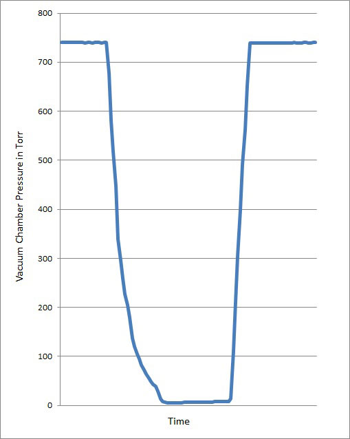
Figure 2. 5 Torr, 40 sec. hold w/controlled pump down.
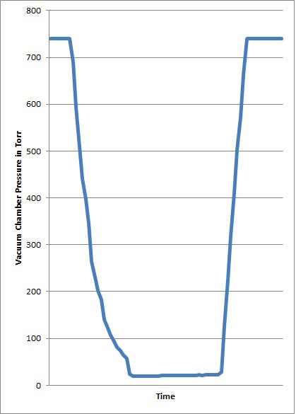
Figure 3. 20 Torr, 30 sec. hold w/controlled pump down.
Equalization rate: The speed at which the vacuum is released and the chamber returned to atmospheric pressure. Currently there is no known adverse effect with high equalization rates, but it takes more time to reach atmospheric pressure with low vacuum levels.
The total time for the vacuum portion of the reflow profile includes the four items listed above, plus the time to transport the board in and out of the chamber. Conducted at the Universal Instruments Advanced Process Lab with the BTU vacuum test board, the two thermal profiles in FIGURES 4 and 5 show the impact of changing the vacuum hold time on the TAL at 20 Torr. A 10 sec. hold results in a TAL of 87 sec., and a 40 sec. hold results in a TAL of 117, a 30 sec. difference. Therefore, there is a 1:1 relationship between hold time and TAL differences.
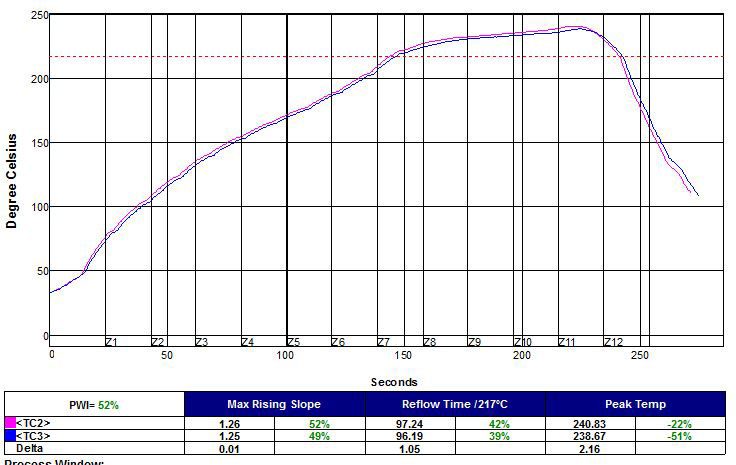
Figure 4. Vacuum reflow profile with 40 sec. hold time.
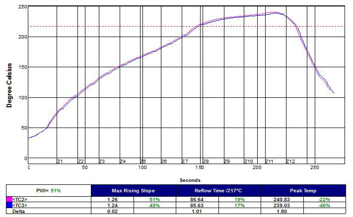
Figure 5. Vacuum reflow profile with 10 sec. hold time.
If the vacuum level is changed from 20 Torr to 60 Torr and maintains a 40 sec. hold, a TAL of 106 sec. results. This 11 sec. difference (117 – 106) is due to the softer vacuum requiring less pump down and equalization time.
Each of these factors has a significant effect on the TAL and a slight effect on peak temperature due to extending time in the heat. In the two aforementioned cases of 20 Torr with 10 and 40 sec. holds, the peak temperature changed by about 4°C. This emphasizes the need to profile boards when any changes to the vacuum cycle or level are made. Thermal profiling is difficult in vacuum systems because the thermocouple (TC) wires are not compatible with the vacuum chamber seal. Therefore, the profiler must be in the chamber during the vacuum cycle. Additionally, the profiler takes up space in the chamber and contributes to the thermal mass being heated.
Preliminary Vacuum Results
Mike Meilunas from the Universal Instruments APL, with assistance from BTU, developed a test board for void studies. The board included QFNs/MLFs with various sized thermal pads, resistors, and D2PAKs, etc. (FIGURE 6). A study was designed to evaluate the affect of vacuum levels and hold times on voids with SAC 305 solder paste from numerous suppliers, two board finishes, and various screen configurations.
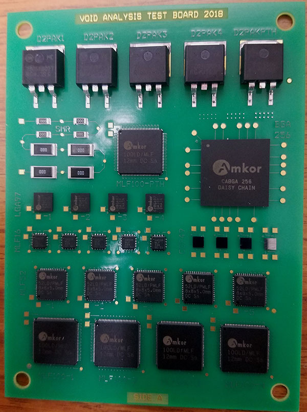
Figure 6. Void study test board.
A ramp-to-peak thermal profile with a linear heating rate of 2°C/sec. and a peak temperature of 240°C was developed, and various levels of vacuum hold times and pump down rates were evaluated.
Although the study has not been completed, preliminary x-ray analysis shows pad size, vacuum level and hold times affect the void level in the thermal pads. FIGURES 7, 8 and 9 are x-ray images of MFL 100, 52 and 16, showing the effect of processing without vacuum, and processing with 120 and 20 Torr vacuum levels with a 20 sec. hold time.
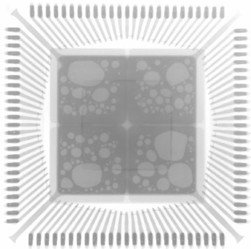
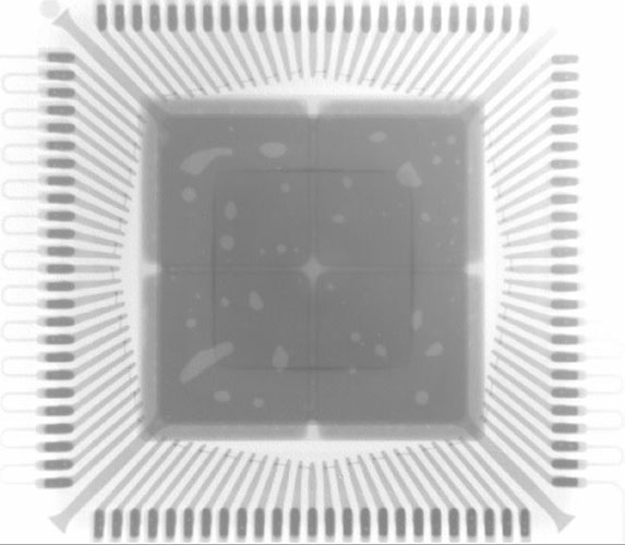
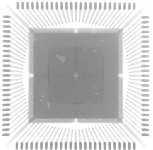
Figure 7. X-ray images of MFL 100. Left: no vacuum, middle: 120 Torr, right: 20 Torr.
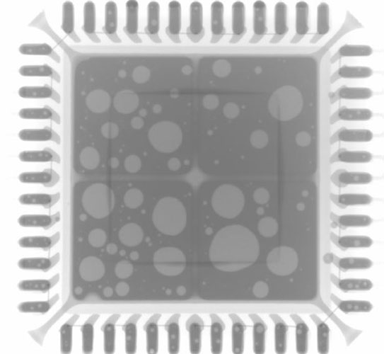
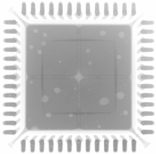
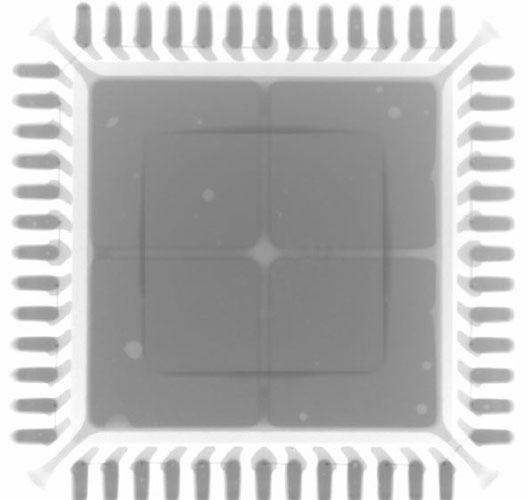
Figure 8. X-ray images of MFL 52. Left: no vacuum, middle: 120 Torr, right: 20 Torr.
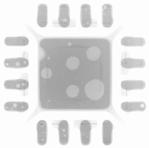
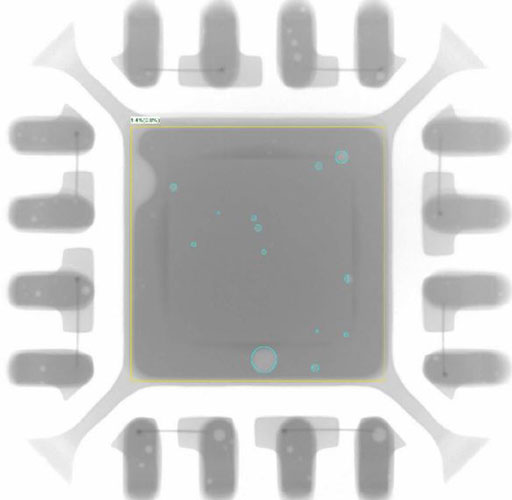
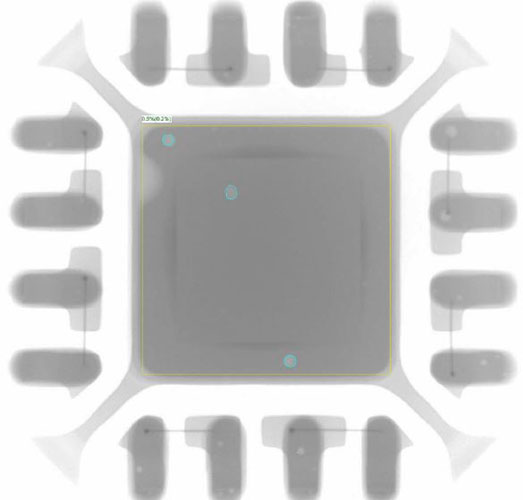
Figure 9. X-ray images of MFL 16. Left: no vacuum, middle: 120 Torr, and right: 20 Torr.
TABLES 1 and 2 show the effect of various hold times and vacuum levels. In Table 1, the vacuum level is held constant at 20 Torr, and the hold time is varied from zero to 40 sec. In Table 2, the hold time is held constant at 20 sec., and the vacuum level is varied from no vacuum to 6 Torr.
Table 1. Effect of Changing Hold Time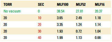
Table 2. Effect of Changing Vacuum Level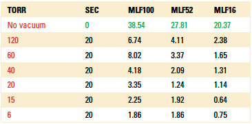
Conclusions
Preliminary results of this trial show vacuum reflow is an excellent way to decrease the void level in thermal pads of MFLs. Levels below 5% were obtained with hold times of 20 sec. and vacuum levels of 20 Torr. Additionally, it was a surprise to learn relatively soft vacuum levels of 120 Torr and short hold times can significantly lower void levels.
Additional results will be published by BTU International, The AREA Consortium and the Advance Process Laboratory at Universal Instruments Corp.
Acknowledgements
Michael Meilunas, Universal Instruments, needs to be thanked for his help in designing the board, collaboration in determining the experiments and running the trials. Also, Arvind Srinivasan Karthikeyan, Auburn University, for running the trials and analyzing the void level in the many solder joints.
Ed.: This article was originally published in the Proceedings of SMTA International, October 2018, and is reprinted here with permission of the author.
is manager, process technology at BTU International (btu.com); fdimock@btu.com.


Press Releases
- Altus Group Invests in Major Headquarters Expansion to Showcase Complete Turnkey Manufacturing Capability
- ViTrox Americas Welcomes Eric Cruz as Technical Support Engineer
- ECD Strengthens Engineering Team with New Software Development Hire
- ViTrox Americas Welcomes Doug Ennis as Senior Field Applications & Service Engineer