

2005 Articles
Parameters of Reflow Encapsulation
"No-flow" materials cut four steps, including one dispensing step and a reflow pass.
Reflow encapsulant (also known as no-flow reflow) combines both tacky flux and underfill, creating a one-step dispensing process. As seen in Figure 1, four of the seven process steps are eliminated, requiring only a single dispensing step. Only a single-pass reflow is required, using a standard SnPb profile to solder the eutectic bumps and cure the underfill epoxy.
Dispensing. Unlike traditional underfills, most reflow encapsulants do not require the substrate or the needle to be heated. As with many dispensing applications, the size of the needle is based on the size of the component. However, for most FC processes, a 23-gauge needle is recommended.
The size of the component also determines the amount of volume required when dispensing the reflow encapsulant material. Table 1 shows examples of typical FC body sizes (in mils or mm) and the volume required. Table 1 also describes the proper dispense patterns based on component size. Shapes such as a dot or asterisk (cross) are common to compression flow processes. These patterns permit domed deposits, minimizing the chance for voiding, which is commonly caused by the placement of FCs or CSPs. A dot configuration is typically applied for dies smaller in size, and the asterisk shape applies to larger dies. Figure 2 shows an example of how these geometries appear from top and side views.
 FIGURE 1: No-flow reflow encapsulants cut the number of process steps to three from seven.
 |
 FIGURE 2: Top and side views of dot configurations.
 |
Die placement setting. The placement setting is important to the reflow encapsulant process because it facilitates the comprehensive flow of the material. Table 2 describes recommended parameters for placing an FC or CSP package. Figure 3 illustrates how a die component would place on an asterisk (cross) shaped pattern.
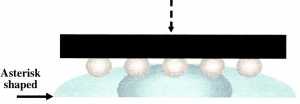 FIGURE 3: Placement of a FC or CSP on an asterisk (cross) shaped pattern.
 |
Reflow profile settings. Modern reflow encapsulants are engineered to facilitate a single-pass reflow process using a standard Sn63Pb37 flux soak profile. This profile (Figure 4) will solder bumps to pads and encapsulate them. This works in conjunction with other SMD components that are populated and soldered with the standard solder paste.
 FIGURE 4: Sample reflow profile.
 |
Storage and handling. Storage is similar to most encapsulating materials – at least a -40°C environment until the expiration date. The pot life is the same in that it cannot be at room temperature for more than 24 hrs.
The material should also be thawed according to manufacturer recommendations. Table 3 shows a sample “time to thaw” using a Kester reflow encapsulant. Most of these times are standard; however, check with the manufacturer for precise thaw specifications.Material should be used completely or discarded rather than frozen and stored for reuse.
The American Competitiveness Institute (aciusa.org) is a scientific research corporation dedicated to the advancement of electronics manufacturing processes and materials for the Department of Defense and industry. This column appears monthly.


Press Releases
- Altus Group Invests in Major Headquarters Expansion to Showcase Complete Turnkey Manufacturing Capability
- ViTrox Americas Welcomes Eric Cruz as Technical Support Engineer
- ECD Strengthens Engineering Team with New Software Development Hire
- ViTrox Americas Welcomes Doug Ennis as Senior Field Applications & Service Engineer