

2005 Articles
Switching to Pb-Free: Wave Soldering
How to adjust conveyors, pots, preheaters and solder modules for Pb-free processes.
Per the RoHS directive, “Member States shall ensure that … new electrical and electronic equipment put on the market does not contain lead, mercury, cadmium, hexavalent chromium, polybrominated biphenyls (PBB) or polybrominated diphenyl ethers (PBDE).” The term “put on the market” needs clarification, as manufacturers of electronics equipment may not be certain about its implications. We inquired at the Ministry of the Environment in Berlin and received the ruling that “put on the market” means delivery of the product to the end-customer.
This clarification makes it all too obvious that industry has to set its own target dates depending on the time it takes to bring product from manufacture to the customer. Furthermore, it will be important to clear all intermediate product that contains lead from the pipeline prior to this date, or to ensure that such product is delivered only to customers outside the EU where the directive does not apply and to customers that have not specified Pb-free product.
Of course, manufacturers may continue to use lead in products that will not be put on the market in the EU after July 1, 2006. Whether this exception will make things easier for industry is for the individual manufacturer to determine.
Those considering converting their soldering systems have to ask, Are the new systems compatible with Pb-free soldering? That means first determining what “Pb-free capable” really means. Opinion might be shaped by whether you sell or buy such equipment. What a vendor considers Pb-free “capable” might not meet your process requirements.
Effects on equipment must be distinguished according to the type of Pb-free solder to be used. Fundamentally, there are two directions to choose: either alloys with substantially lower melting points or alloys with substantially higher melting points. Those alloys with lower melting points (usually bismuth solders) also exhibit a much lower presence of tin (around 50%). Typically the tin content can be compared to that of eutectic SnPb solders.1
Alloys that melt at higher temperatures have a tin content above 90%. In cases such as SnCu, copper, at 0.6%, could be interpreted as an impurity. The high tin content makes itself felt especially where liquid solder is encountered. Tin acts as the “aggressor.” It is the metal that causes the chemical reactions during soldering. The mechanism can be described as the creation of an intermetallic and then the dissolution. This leaching effect causes two problems in equipment:
It corrodes machine parts, especially machine parts that move or where the solder has a high flow rate (as friction enhances the chemical action) (Figure 1).
It contaminates solder (Figure 2).
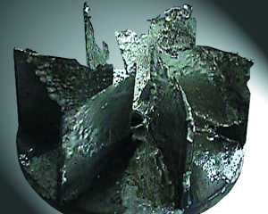 FIGURE 1: Corrosion of an uncoated impeller wheel of a wave soldering system caused by Pb-free solder.
 |
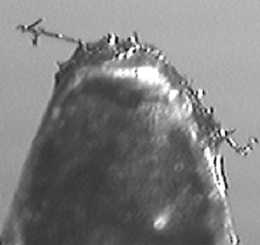 FIGURE 2: Iron intermetallic crystal, a form of solder contamination.
 |
When examining present equipment, keep in mind the alloy desired for use and the possible detrimental actions of tin at a higher temperature and higher content percentage. And materials are just one consideration. It is likewise important to ensure that equipment meets all other process requirements needed to solder with no-Pb solders.
The wave-soldering machine consists, in essence, of these parts:
Conveyor.
Fluxer.
Preheaters.
Soldering module.
Control unit.
Assuming use of a low melting alloy with normal tin content, little will need to be changed. The decreased wettability of all replacement solders lends itself to equipment with nitrogen capability. The absence of oxygen improves wetting. At the same time we reduce the amount of dross and hence cost. A comparison of dross data for different alloys and the cost of these alloys is enlightening.
Depending on the amount of bismuth in the alloy, the metal can expand when solidifying. There is a danger of cracking the pot if no precautions are taken. These may entail either ensuring that the solder will never freeze (power outage) or using a solder pot that compensates for the expansion.
Early experiments have shown that when using bismuth solders, the flux should be substituted with one more suitable. Make sure that the fluxer is low maintenance and capable of controlling the amount of flux applied.
Moving to an alloy with a higher tin content and higher melting point stresses the entire machine. Here’s a detailed look at all the machine’s components.
Conveyor. The most important attributes are smooth operation, parallel rails and chains/fingers to hold boards securely. The designer of conveyors for Pb-Free solders must understand the implications of a higher melting point (and thus even higher temperatures in the preheater), and the lower density of the solder.
Ensure that there is no chance of rail bending or warpage when heated and that greases used on the conveyor are compatible with higher temperatures. The “springiness” of the fingers or solder pallet have to account for the PCB expansion, which will be increased by some measure (follow component manufacturer recommendations to limit the temperature rise from preheat to liquid solder).
The lower density of the solder will affect the peelback of the solder at the exit of the wave. If approximately the same conditions as for Pb-bearing solders are to be achieved, measures have to be introduced to compensate for the lower weight. This can be achieved either by a steeper inclination of the conveyor or some other means; e.g., a different nozzle design. A simple vector diagram shows that a steeper conveyor angle improves the rolling effect of the solder peelback in direction of travel. If we manipulate the gravitational pull, angles between 7-9° may be required. Other properties that play part in the proper peelback are: viscosity, surface tension and naturally the flux.
ýhe disadvantage of increasing the conveyor angle is the height difference between entrance and exit. Handling with periphery units – i.e., integration of the soldering system into a production line – therefore might become a problem. To improve the flow properties of Pb-free solder alloys without changing the conveyor angle, the solder nozzle can be sloped up to 2°. This causes a steeper angle, resulting in a higher flow speed of the solder alloy, which neutralizes the poorer wetting properties of Pb-free solders (Figure 3). Compared to the angle adjustment of the conveyor, changing the solder nozzle angle has a decisive advantage: the wetting length and time are maintained and the solder pot height needs no readjusting.
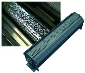 FIGURE 3: Solder nozzle that forms a turbulent wave (courtesy SEHO).
 |
New nozzle designs can also help keep the conveyor angle at the traditional slope. As modified fluxes are possible, ensure that the machine can keep these fluxes out of the conveyor system. Gumming up of chains and bearings requires high maintenance.
Fluxer. An intensive search by chemists has not uncovered any activators more suitable than those presently in use. There are better chemicals, but they are either far too expensive, too rare, hard to come by or toxic, or possess other undesirable properties. Hence, we seem to be stuck with the di-carbon series of acids. With their point of disassociation of about 160°C, they are not suited to the thermal requirements of higher temperature Pb-free processes. It is not only the melting point of the solder that makes their application problematic, but the stringent requirements of many component manufacturers. During wave soldering preheat temperatures may be increased to a level at which fluxes will have difficulty coping. Fluxes would fail unless countermeasures are taken. The most common adjustment proposed is to increase the rosin content and decrease solvent. Switching the sequence of fluxing and preheating, as is done by some selective soldering machines and for some applications in Japan, could be considered.
One cannot help but wonder whether the move to Pb-free will also entail a certain reawakening of cleaning operations.
With such changes in flux makeup, the fluxer has to cope with higher viscosity and higher contamination. Proper exhaust – perhaps even removal from inside to outside the machine – will ensure maintenance is kept at a minimum. A separate fluxing module in front of the soldering machine offers various advantages. First, this ensures minimum contamination of the process area. Further, moving the fluxing module outside the machine offers more room to increase the preheat area, a “must” in case the conveyor speed cannot be reduced.
Preheaters. The preheater’s main function is twofold: measured temperature increase (gradient) of the assembly and achieving a targeted temperature prior to entering the molten solder. Today, thermally complex assemblies are heated with a gradient of between 0.5 and 2.0 K/sec. Making a few basic assumptions we will make a simple calculation:
Solder temperature: 285°C.
Temperature rise from preheat into liquid solder <100 K.
Conveyor speed: 90 cm/min.
When soldering with SnPb the solder temperature was 250°C. In that process we preheated the board to approximately 110°C (measured on the top of the laminate) prior to entering the solder. For Pb-free, we thus would have to achieve a temperature of about 145°C on the assembly – perhaps 160-170°C on the bottom of the assembly.
Room temperature: 20°C.
Using these assumptions, the temperature increase comes to 120 K. If a gradient of 2 K/sec. is used, the assembly must dwell in the preheat for 70 sec. For a gradient of 0.5 K/sec this amounts to 280 sec. – not including a “plateau,” should that be necessary to evaporate solvents (e.g., water). The chosen conveyor speed of 90 cm/min translates to a length of required preheat of 105 cm; however, for a gradient of 0.5 K/sec the total length of preheat needed would be 4.20 m. Not many pieces of equipment would meet that requirement.
As an alternative, the conveyor speed could be reduced, at least in the preheating area (split conveyor), so as to not negatively affect the contact zone in the solder. Reducing the conveyor speed may be possible in many applications, but if no slack time is available during production it would result in reduced throughput. First, check whether the configuration of the preheat area can be changed; e.g., by installing more powerful preheat modules (quartz or convection instead of IR). By removing the fluxing module into a separate module, the preheat zone can be enlarged.
Solder module. The most critical part in a wave soldering machine is the unit that contains and pumps the molten solder. Typical 305 or 316 steel is not resistant enough to cope with the aggressiveness of tin at elevated temperatures. For some time companies have experienced substantial problems in high temperature applications. Those parts that are subject to movement and possibly friction suffer the most. Pumps, impellers and some parts of the wave formers show deterioration very early (Figure 1). Certain areas of the walls also get attacked.
Some metals seem impervious to leaching by tin (e.g., Hastelloy) but such material is proprietary, expensive and difficult to weld and cut. Thus, wave equipment manufacturers have concentrated on coatings for their pots. What we see in the field is the entire range of experiments, some more successful than others. Many have been tested only under laboratory environments, as they may be up to the task if left undisturbed. However, in production, pots and pumps are abused. Machines can be scratched by screwdrivers during maintenance, and pumps knocked against concrete floors to dislodge stubborn dross particles. If such treatment is accounted for, few coatings that would endure the two-pronged attack of inconsiderate treatment and leaching by high temperature tin. Even the best coating will be “undereaten” if cracked or chipped.
Pot treatments range from simple painting with Teflon (not recommended) to impregnating with titanium-nitrate to ceramic coatings. An in-depth discussion with the manufacturer is highly recommended. Figure 4 shows a composite coating developed by SEHO that has been used successfully for several years and is suited for all known Pb-free solder alloys.
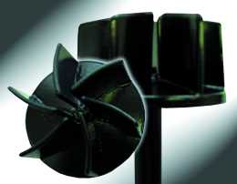 FIGURE 4: Protective composite coating for parts that come in contact with liquid solder.
 |
The increased cost of dross alone justifies use of an inert atmosphere. Working without dross reduction measures would be too expensive (Table 1). The improved wetting performance under nitrogen is a fringe benefit, although absolutely recommended even for other Pb-free soldering processes. Without nitrogen, even higher process temperatures would be necessary, something the materials used would not forgive easily.
A final word about pot size: the larger the pot, the easier it is to generate a flow with little turbulence and greater depth. It also will take longer to exceed dangerous contamination levels. However, filling a large pot with Pb-free solder will be more expensive.
References
V. Schroeder, et al., “Applicability of Bi-42Sn-1Ag Solder for Consumer Products,” IPC Apex Proceedings, March 2002.
Bibliography
A. Rahn and T. Raisch, “Lead-free Soldering of BGA Packages,” The Fifth International IEEE Symposium on High Density Packaging and Component Failure Analysis in Electronics Manufacturing, June 2002.
C. C. Dong, et al., “Effects of Atmosphere Composition on Soldering Performance of Lead-Free Alternatives,” Nepcon West Proceedings, February 1997.
A. Grusd, “Integrity of Solder Joints from Lead-free Solder Paste,” Nepcon West Proceedings, February 1999.
Ed.: This is the second in a four-part series. Future articles will look at reflow and selective soldering equipment, and process changes.
Markus Walter is technical director of SEHO GmbH (seho.de); markus.walter@seho.de.


Press Releases
- Changes in Incap’s Management Team: Incap updates its leadership model to support its growth strategy
- Niche Electronics Celebrates Completion of Florida Expansion
- Microscreen Names Nik Thomas Director, Expands Leadership Role Amid Continued Organizational Growth
- W&S Enters New Growth Phase Through Strategic Partnership and New Leadership