

Pin None?

Properly interpreting the pin one location can be the difference in placing the part.
You would think that in this day and age, all our machine friends would be smart enough to just know what we're thinking. Unfortunately, that's still not the case. There are some instances when we have to put in extra effort to make our intentions clear. Locations and polarities on your printed circuit board are a particularly good example. Ambiguous polarity markings and pin one markings printed on your PCB can wreak havoc on your prototype. In theory, for SMT parts, it really shouldn’t matter; the centroid would take care of the placement orientation. But, you may have noticed that it’s not a perfect world. It took me awhile to figure that out, but I have finally concluded as much.
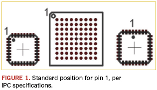
It’s not uncommon for the CAD library part to have the wrong zero degree rotation orientation. The IPC specified location for pin one orientation for square chips like QFPs, QFNs and BGAs is either the upper left or middle top (Figure 1). (Check out our centroid guide at http://i.screamingcircuits.com/docs/understanding-the-centroid-file-r2-2.pdf for more detail.) If it’s wrong in CAD, the centroid will be wrong, as will everything downstream. That’s why markings on the board are still important. Sometimes human intervention still comes through in the end.
What do you do if your part is ambiguous, though? This particular chip (Figure 2) has three markings that could be interpreted as pin one indicators. At first glance, I’d assume it’s the dot in the center top. It would match with the text. However, there is a white dot in the lower left that could be pin one indicator, which would mean, in this case, the CAD library component had the incorrect zero rotation orientation.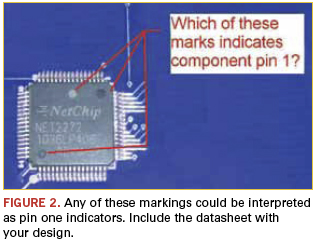
Datasheets aren’t always easy to find. The one for the part shown is behind a registration wall. If you have a part like this, it’s really helpful if you include some documentation when you send your files to your assembly house. I found the datasheet for this particular part and was able to confirm that it is correct as placed with pin one down in the lower left (90⁰).
Ed.: Read Duane’s blog each week at circuitsassembly.com/blog/.
Duane Benson is marketing manager at Screaming Circuits (screamingcircuits.com); dbenson@screamingcircuits.com. His column appears bimonthly.


