

Can Next-Gen Military Products Beat the Heat?
Thermal management is becoming a common limiting factor in newer technologies.
Ed.: This is the fifth of an occasional series by the authors of the 2017 iNEMI Roadmap. This information is excerpted from the Roadmap, which is available from iNEMI (http://community.inemi.org/content.asp?contentid=51).
Aerospace/Defense products’ high- and low-temperature requirements force improvements in components and materials. Components must operate at both high- and low-temperature extremes without substantial derating or decrease in functional performance, and ideally without additional cost. This can at times require “up-screening” of commercial parts. Electrical interconnections (solder joints and PTVs) must be able to tolerate constant cycling between these temperature extremes for years without failure. Materials such as dielectric laminates, solder masks, adhesives, underfill, coatings, and solder need to perform at high- and low-temperature extremes and over a range of environmental conditions (i.e., moisture and chemical exposure) without degradation. Additionally, reworkable underfill materials are desirable.
Components. Active leaded components range from 0.015" to 0.050" pitch in a variety of package technologies. Active leadless components range from high-ball-count, fine-pitch area array ball grid array (BGA) to low-ball-count, odd-form BGAs, QFNs, and land grid array (LGAs). BGAs range from 1.27mm to 0.65mm pitch. The higher I/O BGAs are typically 1.0mm, and the 0.65mm pitch BGAs are typically low I/O. This trend of increasing solder ball count and decreasing solder ball pitch is expected to continue as pitches go to 0.5mm, 0.25mm and smaller. The LGA is popular due to its package size, but its reliability, specifically with SnPb solder, is still questioned. BGAs come in a variety of configurations, wire-bonded with an epoxy over-mold, flip chip, with a metal heat sink, etc. Several heat spreader designs are used to dissipate heat generated by BGAs. In some cases, these heat spreaders are open to cleaning solvents and conformal coating. Adhesives used to bond the heat spreader to the package are in many cases incompatible with the cleaning solvents used for flux removal or cleaning prior to application of conformal coating, causing the heat spreaders to fall off the component during cleaning. Additionally, cleaning solvents may attack the thermal interface material (TIM) inside the component, affecting its thermal performance. The assembler must ensure the heat sink attach adhesive, TIMs, and cleaning chemistries are compatible. In some instances, there are capacitors or other discrete components internal to the component. These discrete components may have Pb-free surface finishes that must be considered from a tin whisker perspective. In most cases, an exhaustive parts review for the newer components usually pays for itself in scrap reduction and schedule delay avoidance.
All surface-mount components require a low-cycle thermal fatigue analysis for military products, and the thermal expansion characterization of new parts is something our industry frequently investigates beyond what the supply base offers.
Thermal management. Thermal management is typically accomplished with passive conduction cooling. Increasing power densities and demands on thermal management have resulted in various new approaches and a transition from passive to active cooling. COTS products are typically designed for convection cooling, whereas the traditional military box has been designed for passive conduction cooling. Heat sink frames are typically made from aluminum or copper, although the popularity of various composite materials and active (air and liquid flow through) heat sinks is increasing.
Composite materials, although typically expensive, are being used in some cases to improve thermal management but can be used to reduce thermal expansion of the PWB, creating a better match of the thermal coefficient of expansion (CTE) between the PWB and specific components. There is significant interest in the use of nanotechnology materials such as carbon nanotubes to reduce thermal resistance at the various interfaces. Heavy demands have been placed on thermal management techniques with combined use of heat spreaders and heat sinks, resulting in the evolution of several unique assembly requirements and challenges. Based on the power dissipation of many of these new components, thermal management is becoming a common limiting factor in newer technologies.
Most products use rigid PWBs, although an increasing number of applications take advantage of rigid-flex PWB designs. The most common PWB material continues to be high-temperature FR-4 laminate, with polyimide glass used in high-temperature applications. There is niche use of aramid fiber-based laminates when constraint of “x-y thermal expansion” is critical, and Teflon-based materials such as duroid are used for some RF products. There is a growing requirement for specialty laminate materials for HDI PWBs using multiple layers of microvias and requiring multiple lamination cycles. There is limited use of ceramic hybrid substrates, primarily in RF products.
Table 1. Selective Leading-Edge TWG Drivers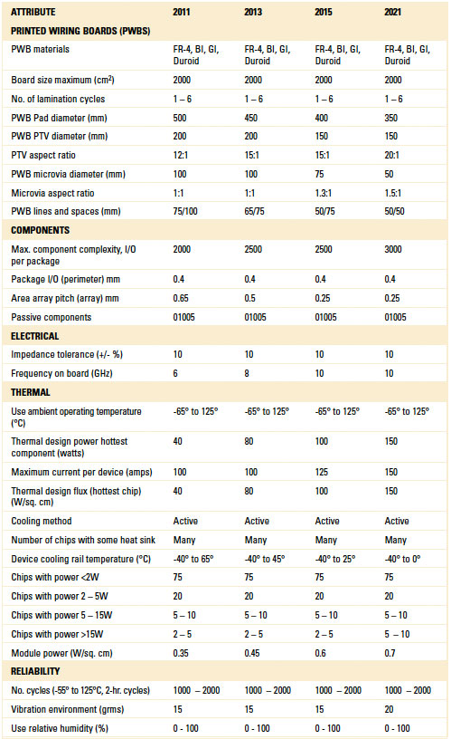
TIMs. There is increasing interest in new and advanced materials for thermal interface materials and heat conduction in all areas of the electronics market, including aerospace and military. While there are obvious similarities, different applications have different key requirements of the TIMs. In all cases, the TIM needs to minimize stress, prevent electromigration of its fillers and maximize adhesion.
Phase change materials (PCM) transition from a solid to a semi-solid phase with heat from the power devices and can completely fill the interfacial air gaps and surface voids, usually under light clamping pressure. The performance is similar to the best of thermal greases and is gaining acceptance in defense and aerospace applications.
While less “runny” than grease, some PCM-based TIMs contain wax and may flow out of tight areas once melt-on temperature is reached. Recently introduced phase change type materials are hot wax-based and will not drip. Since these materials are firm and easy to handle at room temperature, operators have more control when applying the solid pads to a heat sink surface. Compressible phase change pads eliminate trapped air along the interface and are also compressible, conforming to the slight, or large, curvature of the electronic devices.
Polymer solder hybrids provide superior long-term reliability and exhibit the lowest thermal impedance of phase change materials. For optimum performance, the material must be exposed to temperatures above the melting point of contained solder(s) during operation (or by a burn-in cycle) to achieve lowest thermal impedance and highest thermal performance. Upon reaching the required burn-in temperature, the material will fully change phase and attain minimum bond-line thickness of less than 0.001" (0.0254mm) as well as maximum surface wetting. These polymer solder hybrids are typically used in microprocessors, graphics processors, chipsets, memory modules, power modules, and power semiconductors. At higher temperatures, the material may flow when oriented vertically; this does not affect thermal performance, but should be considered if appearance is important.
and co-chair the Aerospace/Defense Product Emulator Group (PEG) of the iNEMI Roadmap.


Press Releases
- Javad EMS Upgrades Through-Hole Soldering Capacity with New SEHO PowerWave System
- Sharpen Your Selective Soldering Skills with Kurtz Ersa's July VERSAFLOW 4/55 Training
- Omron Advances Inspection Technology with NVIDIA Omniverse and Metropolis
- Seika Machinery’s SMI 2026 Webinar Series Continues with Focus on PCB Cleaning Before Solder Paste Printing