

What you don’t test can hurt you.
One of the most important steps in printed circuit board production is testing. If PCBs aren’t tested, errors and defects missed during the manufacturing process could eventually lead to malfunctions and product failures in the field. After a PCB board is manufactured and assembled, it is tested to ensure no shorts or opens are in the PCB circuitry. All components must be verified for the correct values per the design, proper orientation, and be free of faults (or dead). Inspecting the solder quality of through-hole (PTH) connector leads, large surface-mount technology (SMT) ICs and the balls of a ball grid array (BGA) package can be difficult with standard inspection tools and methods. These verification processes are highly challenging and require a full understanding of the design scope of ECAD tools and the mechanical capabilities of the testing equipment.
Recouping value from excess stock.
If manufacturers understood the true value and opportunity of their excess and obsolete (E&O) electronic component stock, they would take a much more proactive approach to ensure this surplus inventory is not written off and sent to landfill.
In reality, E&O inventory is not an operational inconvenience but a financial opportunity and sustainable responsibility. Provided E&O stock is brand new, unused and in the original manufacturer’s packaging, manufacturers can likely redistribute the parts on the secondary market to another manufacturer for use. This not only recoups value for the redistributing company, but also promotes a circular economy, extending the lifetime value of the materials inside.
Improper paste viscosity and incorrect reflow ramp profiles are just a few of the root causes.
Solder balls are small, spherical metallic balls that can form on circuit boards, typically around the leads or pads of surface mount components. Ranging from just a few micrometers to a couple of hundred micrometers in diameter, these balls form from issues in the soldering process.
If solder balls appear, they can affect the overall functionality of the circuit board. Small solder balls are unsightly and can move components slightly off mark. In the worst cases, bigger solder balls can fall off the surface and deplete the quality of the component joints. Worse, balls can roll onto other board parts, leading to shorts and burns.
Typically, solder balls are located on the side of chip components (Figure 1). Solder balls, which are typically between 0.2mm and 0.4mm in diameter, can occasionally be observed surrounding the pins of ICs and connectors.
- 0.5mm solder balls or larger are typically unacceptable due to the risk of bridging and shorts.
- Even when smaller than 0.2mm, solder balls may not cause immediate issues. They may indicate problems with solder application and can lead to reliability concerns.
- Regardless of size, solder balls are typically not permitted close to high-density areas or important components.
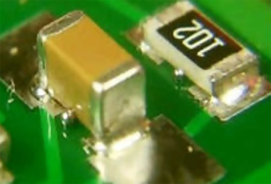
Figure 1. Solder balls formed on the periphery of a passive component.
Always check the specific requirements provided by manufacturers or clients, as they may have stricter criteria based on their applications.
Factors and Solutions
Several factors contribute to solder ball formation.
Moisture. Excess moisture in solder pastes or the bare PCB can lead to the formation of solder balls during reflow. Moisture contributes to this issue in multiple ways:
- Solder paste is hygroscopic, meaning it can absorb moisture from the environment. Improperly stored paste can take on moisture, leading to problems during soldering.
- During reflow, heat causes absorbed moisture to vaporize rapidly, creating steam. This steam can create bubbles in the solder paste. The rapid expansion of steam can disrupt the solder paste, causing the solder to bead up and form solder balls instead of flowing smoothly to create solid joints.
An improper metal-to-flux ratio or poor solder paste quality can lead to solder being expelled and forming solder balls during the soldering process. If the flux content is too low relative to the solder metal, it may not effectively reduce surface tension and facilitate proper flow, leading to solder balls instead of smooth joints. Conversely, too much flux can create an unstable mixture that causes solder to clump and form balls during reflow. Poor quality paste may have inconsistent viscosity, which can result in uneven application and excess solder in certain areas, increasing the likelihood of solder balls.
Extreme temperature variations can alter the viscosity of solder paste, affecting its application and performance. Higher temperatures can make the paste too runny, while lower temperatures can make it too thick. Temperature changes can cause the metal and flux components in solder paste to separate, resulting in an inconsistent mixture that may not perform well during soldering.
Viscosity. Low viscosity solder paste can lead to slumping and the formation of solder balls during the soldering process.
Low viscosity solder paste lacks the necessary thickness to maintain its shape during the reflow process. This can cause excessive flow, leading to solder slumping away from pads and forming unintended shapes. When solder paste slumps, it may lose the defined areas needed for proper solder joints, increasing the likelihood of solder balls forming instead of smooth, cohesive connections. Low viscosity also can disrupt the balance of surface tension, causing solder to bead up instead of spreading evenly across the pads.
Oxidized solder paste. Expired or oxidized solder paste can create solder balls and contribute to leaching effects during the soldering process.
Inconsistent flux activity. Expired solder paste may have degraded flux, resulting in poor wetting and inadequate solder flow. This causes solders to clump and form solder balls instead of creating smooth joints.
Low viscosity. Oxidized solder paste can lose its intended viscosity, leading to excessive solder application and the formation of balls during reflow.
Inadequate adhesion. Degraded paste may not adhere properly to the PCB or component pads, permitting solder to pool and create balls.
Among the mitigation strategies are the following:
- Choose appropriate paste. Select solder paste with the correct composition per product and design requirement for the specific application and printing process.
- Proper mixing. Ensure the solder paste is well-mixed before use to achieve the desired viscosity and consistency.
- Temperature control. Maintain proper temperature and humidity conditions during storage and application to prevent changes in viscosity and oxidation.
Reflow Process
Insufficient preheat temperature can significantly affect the soldering process by causing the flux to evaporate too quickly, which can lead to solder expulsion and the formation of solder balls. With insufficient flux activity, solder may not adhere properly to the pads or components. This leads to solder being expelled from the joint during the reflow, causing it to form balls.
A reflow profile with a high ramp-up rate or a too-rapid temperature increase can lead to solder splattering and formation of solder balls. If the temperature increases too quickly, the flux may not have enough time to activate properly, which is essential for good wetting and adhesion. This results in poor solder flow and ball formation.
Vibrations during the reflow process can dislodge solder paste from its intended position, causing components to move and leading to solder balls forming either on the PCB surface or between solder joints.
Stencil and Printing
Improper stencil aperture design, especially excessive volume or poor gasket seal, can lead to solder ball formation during the reflow process, as the solder paste can creep under the stencil and form beads. If the aperture area is too large for the pad size or if the stencil is not properly gasketed, excess solder paste may be deposited, resulting in the formation of solder balls under the component or on pads.
Guidelines for avoiding solder balls due to printer errors include the following:
- Follow the datasheet. Develop a stencil per component data sheet guidelines.
- Reduce aperture volume. Design apertures slightly smaller than the pads to ensure a good gasket seal and prevent excess paste deposition.
- Optimize aperture shape. Consider using “home plate” or “radiused inverted home plate” (RIHP) apertures to reduce the possibility of “mid-chip” solder balls.
- Ensure proper stencil-to-PCB contact. Ensure a tight seal between the stencil and PCB to prevent paste from creeping under the stencil.
- Use appropriate squeegee pressure. Proper squeegee pressure is crucial to ensure complete paste transfer and prevent paste from being trapped in the apertures.
- Choose the right stencil foil thickness. Thicker foils can be used for larger components or those prone to warpage or coplanarity problems, while thinner foils are better for smaller components with finer pitch I/Os (input/outputs).
Stencil cleaning. Improper stencil cleaning can lead to solder paste residue accumulating, which negatively impacts solder paste application, potentially causing solder balls and other defects during reflow. Regular cleaning of the stencil, or cleaning after a certain number of prints, is essential for ensuring consistent solder paste application and preventing solder ball formation. Adhere to the guidelines in IPC-7526 for cleaning stencils and misprinted boards.
Stencil alignment with PCB. When the stencil and PCB are not properly aligned, the solder paste is printed in the wrong location, potentially depositing paste on areas other than the intended pads. It is important to ensure proper stencil alignment during initial setup only.
Wiped PCB. A misprinted and wiped board can contribute to solder ball formation during reflow. Wiping a misprinted board with alcohol or other solvents can leave residual moisture or solvents that interact with the solder paste during reflow, causing it to splatter and form solder balls. Additionally, the act of wiping can push solder paste into vias or other areas, exacerbating the problem. Instead of wiping, use an automatic cleaning process, like an air spray or ultrasonic cleaner, to remove misprinted solder paste. These methods are more effective at removing paste without pushing it into unintended areas.
PCB and Component Issues
Trapped moisture in a PCB or component can lead to solder balls during the reflow process. When heated, this moisture outgasses and creates steam, which can displace solder and result in the formation of solder balls. It is advisable to store PCBs and components in a dry environment. Bake PCBs before assembly to remove any trapped moisture.
Poorly executed hot air solder leveling (HASL) with nonuniform PCB pad flatness can contribute to solder ball formation, Uneven or warped pads can lead to inconsistent solder deposition. Higher areas may not receive adequate solder, while lower areas may accumulate excess solder.
Control the HASL process to achieve consistent solder coverage, ensuring pads are properly leveled.
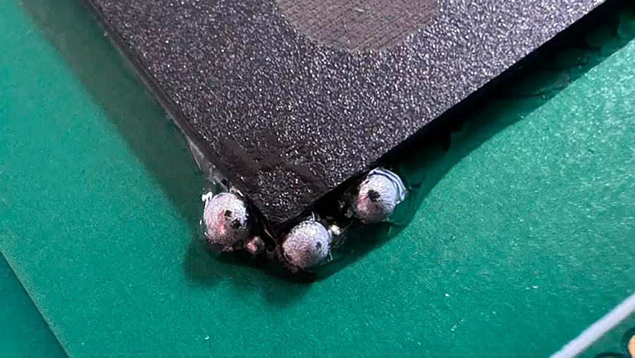
Figure 2. Multiple solder balls formed on the edge of an array package.
High pressure during placement. An often-overlooked factor contributing to solder balls is excessive mounting stress. Applying too much pressure when placing components can compress solder paste beyond its intended limits, resulting in paste being pushed off the pads. This can lead to solder being displaced and forming balls. If the mounting stress is excessive, the solder paste may be forced out of the pad, which can transform into solder balls after the reflow soldering process. To avoid this problem, minimize mounting stress so that components can be accurately positioned on the printed solder paste and pressed down appropriately.
Conclusion
Solder ball formation is a critical issue that can significantly impact the functionality and reliability of circuit boards. Factors contributing to the formation of solder balls include issues with solder paste, reflow process, stencil and printing as well as PCB and component issues. Moisture, paste composition, storage conditions and oxidized solder paste are key contributors to solder ball formation during the soldering process.
Mitigation strategies such as choosing appropriate solder paste, ensuring proper mixing, temperature control and preheat temperature during the reflow process are essential in preventing solder ball formation. Proper stencil design, cleaning, alignment and PCB moisture management are crucial in avoiding solder ball formation during the printing and assembly process.
By understanding and addressing these contributing factors, manufacturers and designers can effectively mitigate the risk of solder ball formation and ensure the quality and reliability of circuit board assemblies.
is deputy general manager at Napino Auto and Electronics (napino.com); m.imtiaz@napino.com.
Ten techniques to ensure a smooth end-to-end process.
From medical devices to monitoring systems, products are becoming smaller, smarter and more complex to manufacture, making mechatronics assembly the bedrock of innovation for forward-thinking OEMs. Modern mechatronics manufacturing no longer focuses solely on mechanical integration; it now fuses electronics, sensors, software and control systems in ways that demand tighter tolerances, smarter testing and leaner processes. Although core techniques remain relevant, recent developments in mechatronics assembly – such as the integration of Industry 4.0 technologies, automation and AI – means more modern techniques are emerging.
To meet the high level of skill, precision, accuracy and consistency that today’s mechatronic assemblies demand, here are 10 advanced mechatronic assembly techniques that ensure a smooth end-to-end process.
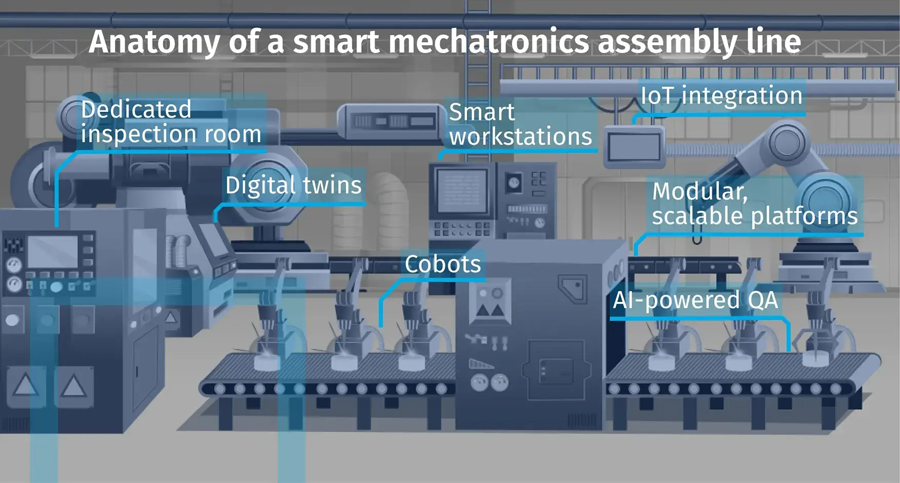
Figure 1. Anatomy of a smart mechatronics line.
1. Organize purchasing teams into clear commodity groups. Because mechatronic assemblies tend to feature bespoke metalwork, you must build a broad and robust supply chain that delivers high-quality parts as needed. A well-structured procurement team is the first line of defense against supply chain disruptions, component shortages, quality issues and pricing volatility. By organizing experts into commodity groups – mechanical, electronic, plastic, PCB, etc. – each buyer can focus their skills and efforts on one specific area. For example, one person may purchase sheet metal while another is responsible for all the machined parts. This approach encourages excellence, as each specialist can develop deep supplier relationships and sourcing strategies for each category. This leads to better negotiation power, supply-chain resilience and effective design feedback loops.
2. Set up an inspection room. A dedicated inspection room ensures that each part of a mechatronic assembly – especially safety-critical components – looks and functions as specified, with consistent visual, dimensional and functional checks at every stage of the process.
Often, builders won’t find issues until the physical build takes place as, individually, the parts produced will pass initial quality checks. But problems such as wrong dimensions, missing cut-outs in metalwork, incorrect paint or anodizing finishes, scratches to front panels, etc. can and should be picked up beforehand.
The inspection room should include calibrated equipment like height and surface measuring instruments, digital calipers, mechanical micrometers and high-magnification microscopes. Any issues found either at material level or during build should be fed back to the purchasing and engineering teams to implement corrective actions.
3. Invest in 3-D CAD modeling packages. It is well worth investing in a 3-D computer-aided design (CAD) modelling package to support collaboration among design, manufacturing and quality teams. This software reduces the time it takes to design a product and improves quality and delivery during the build process. Many software packages available today simulate real-world scenarios, which bring a design to life. This process helps to identify potential tolerance issues during the mechatronics build, enabling prevention before work starts.
4. Implement a robust test strategy. Testing ought to be at the heart of everything an OEM does. After all, if the product doesn’t work properly, the entire manufacturing process is rendered useless. A good test plan reduces field failures, accelerates compliance approvals and feeds back into design improvements. Testing is especially important in mechatronics manufacturing because the addition of moving parts requires them to operate at high and low tolerances while interacting with stationary parts, adding complexity. Therefore, a robust test strategy ensures the product is functionally tested to meet the end-user’s requirements.
5. Adopt digital twin technology. Digital twin technology creates a virtual replica of the product and the production process, permitting simulation, monitoring and optimization of mechatronic assemblies before they hit the physical production line. In mechatronic assembly, this means virtually assembling components to test tolerances, thermal performance and interdependencies between mechanical and electronic systems before committing physical resources. This helps proactively identify and mitigate issues during the design or prototyping stages, avoiding costly revisions in later production phases.
6. Set up smart workstations with IoT integration. Smart workstations combine digital guidance, torque-controlled tooling, barcode scanning and connected sensors to create a closed-loop manufacturing environment. Each assembly step is validated in real time, and deviations are flagged instantly, improving traceability and reducing operator error.
IoT integration, a hallmark of Industry 4.0 technology, takes it a step further by connecting machines, materials and personnel into a real-time data network. For example, when a part is assembled outside of its specification at any point, it’s instantly logged and reported, supporting real-time corrective action and data-driven process refinement.
7. Use modular, scalable assembly platforms. A modular platform strategy transforms rigid manufacturing setups into reconfigurable, future-ready assembly environments. Workstations are designed to be retooled or repurposed quickly, making it easier to switch between products or scale production based on demand without sacrificing throughput. This is ideal for OEMs that need to pilot new products, support multiple variants or respond to fluctuating order volumes. With this approach, a new product can ramp up in weeks, not months, while maintaining the highest quality and traceability standards.
8. Deploy advanced cobots with vision systems. Modern robotic systems, particularly collaborative robots (cobots), execute high-precision tasks in environments that demand both flexibility and repeatability. For example, they can selectively solder, pick and place components, automatically fasten screws and even dynamically inspect products. Paired with machine vision systems, cobots check, measure and manipulate components with micrometer-level accuracy. This is especially useful in mechatronic assemblies where tolerances are tight and product configurations vary frequently.
9. Use AI-powered quality assurance tools. AI-driven visual inspection tools can now outperform the human eye in inspection speed, consistency and defect detection. Machine learning models trained on thousands of images can instantly spot anomalies like microcracks, missing components or solder bridges and even under varying lighting or orientation.
Integrating AI across several inspection points can help close the loop among design, process and quality faster, thus improving first-pass yield rates and accelerating root-cause analysis and regulatory documentation.
10. Adopt a closed-loop feedback system. A closed-loop feedback system, powered by Six Sigma and lean manufacturing principles, captures data from manufacturing and test stations, links it back to design and process teams and triggers updates in real-time. This creates a living manufacturing environment where issues are resolved before they escalate, and lessons learned are instantly embedded into future iterations.
For example, if the system identifies recurring failures in a specific connector, engineering can evaluate the root cause and adjust design tolerances or sourcing decisions accordingly. This shortens development cycles, reduces product revisions and makes for a more agile supply chain.
Conclusion
Whether developing a next-gen surgical device or a smart industrial controller, mechatronics assembly is a complicated process; the combination of moving parts and bespoke metalwork means that there is a lot to take into account. It’s vital to adopt modern techniques to ensure a successful mechatronics assembly process, from concept to full-scale production.
Ed.: This article was first published in the Escatec EMS Review and is republished with the author’s permission.
is director of corporate marketing at Escatec (escatec.com); neil.sharp@escatec.com. He has held a range of leadership positions in sales, marketing and customer service with over 25 years’ experience in electronics manufacturing services and component distribution.
A manufacturer’s perspective on determining parts layout.
A land pattern refers to the footprint or layout of surface-mount components on a printed circuit board (PCB). It includes the arrangement of pads, or lands, to which component leads or terminals will be soldered. An accurate land pattern is crucial for ensuring reliable solder joints, proper alignment of components and optimal electrical performance of the circuit. Most electronic component manufacturers provide detailed specifications and guidelines for creating land patterns specific to each component, which should be followed closely during PCB design.
Catching the stray solder paste.
Manufacturing defects in surface mount technology (SMT) assembly can prove persistent and challenging to diagnose without a structured troubleshooting approach. When a contract assembler encountered recurring solder balling on a single capacitor, initial efforts to correct the issue through reflow profile adjustments proved ineffective. This case study demonstrates how a systematic troubleshooting framework can effectively identify and resolve assembly defects.

Press Releases
- Altus Group Invests in Major Headquarters Expansion to Showcase Complete Turnkey Manufacturing Capability
- ViTrox Americas Welcomes Eric Cruz as Technical Support Engineer
- ECD Strengthens Engineering Team with New Software Development Hire
- ViTrox Americas Welcomes Doug Ennis as Senior Field Applications & Service Engineer