

2013 Articles
Benchtop was in and integration was all the rage at the annual North American trade show.
At IPC Apex Expo this year, small was big.
The annual trade show, the largest assembly equipment event of its kind in North America, kicked off in late February to strong crowds and a positive vibe that belied the unseasonable chill in the San Diego air.
A number of products were introduced that will challenge previous designs for market share. Universal Instruments, Panasonic, Europlacer and Fuji were among those with new placement machines. Speedline showed the latest Camelot dispenser and Momentum printer, both of which are smaller than previous models. BTU proudly discussed Dyanmo, a lower wattage, smaller platform for convection reflow soldering. On the test and inspection side, several benchtop analyzers and testers were unveiled by companies big (Agilent, CyberOptics) and small (ASC).
As with last year, sensors and lasers are all the rage. Precision and speed often improve on different curves, and judging by the new machines this year, the current emphasis is more on the former. And many equipment vendors have retooled their offerings for the high mix, high complexity market.
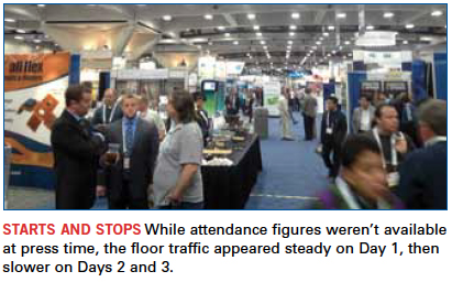
Floor traffic, always the arbiter of a show’s success, appeared steady throughout the first day, never overwhelming but always busy and noisy. The second day started slower than the first before picking up in the late afternoon, giving exhibitors more time to dwell on the state of the industry economy. Day 3 was fairly quiet.
Several exhibitors noted that visibility remains clouded for 2013, with those supplying to the automotive sector the noticeable outliers. David Wolff of bare board distributor NCAB noted a change in supply chain practices, saying that OEMs are “absolutely taking control of (bare) boards again.”
Software
Aegis very proudly rolled out FactoryLogix, a software suite aimed at coordinating the entire manufacturing enterprise outside of accounting and R&D, including box build and system integration. The new suite tracks NPI progress, and can be adapted to individual manufacturing sites around the world. It also handles mechanical CAD as well as EDA. And, it’s configurable, but doesn’t require programming. As president Shaun Black explained, “We wanted to get the customer integration costs – such as coding – out, and the configuration in.”
Printing/Dispensing
PVA rolled out the VPX-2K 2-component dispensing pump.
Speedline’s Momentum Compact printer shrinks the footprint of the previous generation. And its new Camalot Prodigy has a narrower footprint but loses none of the functionality, boasting a 30µm accuracy at full system speed, and coming in single or dual lane versions.
DEK refined its VectorGuard stencil, increasing the tension some 45% to make it easier to print 01005 components.
Asymtek is adding a UV curing oven that features an arc lamp instead of microwave as a heat source.
Placement
Universal’s Fuzion was likely the most talked-about new placement platform. It features two head types with overlapping component capability, meaning engineers won’t need to change out the heads. It supports up to 144 feeders, which is a big jump in capacity, and reportedly has a changeover time of 15 to 20 minutes. The IPC-9850 rate is up to 30,000 cph, and the component range is 01005 to 150 x 150mm, depending on which machine is used. All in all, a very flexible new mounter has arrived.
Panasonic also had an interesting development with the AM100, a single head (single beam) mounter capable of placing components ranging from 0402mm to 120 x 90 x 28mm, large connectors, odd-shaped parts, and advanced packaging types such as PoP. It also featured non-stop changeover, allowing the next product to be prepped while production is running.
Hitachi’s Sigma F8 was another machine that is forcing a lot of functionality (four 15-nozzle heads) into a smallish (1,280 x 2,240mm) footprint.
It wasn’t all just surface mount. Panasonic debuted the AV123 axial inserter, which features 30,000 cph performance on a small (there’s that word again) platform.
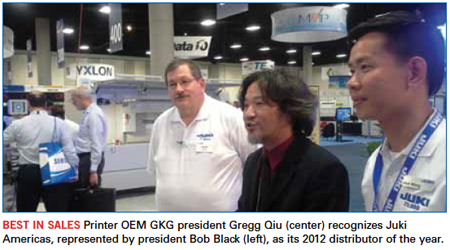
Juki’s Bob Black indicated a new JM series would be out in June. Juki also happily accepted GKG’s 2012 Distributor of the Year award.
Siplace and Panasonic joined Universal as placement companies indicating growth in 2012.
Soldering/Materials
ECD has a new sensor-based system that aggregates humidity data from up to 25 points in the factory and consolidates it in a mobile app. FCT Assembly discussed NanoSlic, a cylane molecule-based nanocoated stencil said to retain the coating longer than phosphorus-based versions. (Expect to see more cylane-based flavors as the second-generation nanocoats appear.) It’s due for release in June. Count DEK among those that expect to see more coatings introduced, reporting “great results” by customers.
BTU’s Dynamo could be a game changer. (We say “could,” because the machine won’t be shown until April.) It’s a new convection reflow platform with 8, 10 or 12 zones, capable of running air or nitrogen, but with 20 to 25% less energy use than its Pyramax cousin. BTU cut the energy by reducing the number of blower motors in the heater section, instead placing one outside the chamber where it can handle two zones at once.
Finetech showed a slick tool for reworking package-on-package and QFNs.
It’s been awhile since solder material companies used a trade show to roll out new products. Instead, they leverage the events to formally announce products that were developed for specific applications or customers, in some cases, months or years earlier. Apex was the first show we saw Enthone and Alpha under their new corporate banner, Alent. There was one revelation, however: Henkel is rebranding its surface mount materials under the Loctite name.
Finally, the IPC-A-610 meeting drew 74 attendees, a big number even for the IPC’s largest task group. Of some concern, it appears the solder types have been removed from the latest J-STD-006, rendering the document as a listing of solder alloys, but not much more.
Test/Inspection
As users grapple with smaller products and tighter test access, the test strategy is inherently changing. Boundary scan is becoming more prevalent, as is BIST for chip-to-chip communication.
CyberOptics, ASC (AP500, a fully automatic benchtop 3D SPI), and Newly (n=1 first-article inspection, plus board resistance and capacitance checks) were among those pushing smaller footprints.
Koh Young has a deal with KIC to jointly develop a tracking system to report profile and joint data, which then will be displayed in Koh Young’s pre- and post-reflow results.
Mirtec’s switch to CoaxPress cameras boosted the speed of its MV-9 series, which includes all LED and 2D/3D AOI, to 25 GB/sec., up from 5 GB/sec.
Nordson Dage has a new, undisclosed platform due out at Nepcon China.
Fabrication
We wish there was more to discuss on the fab side. As noted in past years, the Asian-based trade shows (JPCA, CPCA, HKPCA) are the top sites for developments in printed circuit board fabrication. There were, however, a couple of developments that caught our eye.
Remember the ESI mechanical drill team? They are regrouping at Interdyne, and the early results are impressive. Consider a granite base, six-head mechanical drill with a so-called laminated “wing” that moves in the Y axis while the spindles move in the X. The linear motors are tied directly to the 250km spindles. The new drill uses standard bits and reportedly is capable of 2 mil holes at a rate of 1000 hits/min., and can drill a 441 mil backpanel with 90 mil thick copper at 110 hits/min. When did the last new drill technology come out?
Also, Rainbow Technology discussed its automated vertical develop/etch/strip line, which runs on 4kW of power, has full automatic handling, and requires no solvents. The throughput is 90 panels/hr., and beta testing begins this year.
As always, the show is too large to detail every new development here. For the full list of new assembly products and materials, go to http://www.circuitsassembly.com/cms/ipc2013.
For fabrication-related products and materials, go to http://www.pcdandf.com/cms/ipc2013.
While Apex likely remains second to Productronica as a site for assembly equipment launches (its fabrication-based Expo half has long since ceded that designation), we did note more than a few exhibitors reporting they were holding launches until Nepcon China in late April. Outliers or the start of a trend? It’s something to watch.
High Hopes for 2013 NPI Winners
The annual Apex trade show represents the honorary start to the new year. It’s also an end of sorts: the culmination of the rookie year for products introduced at the previous Apex.
Each year at Apex, PCD&F and CIRCUITS ASSEMBLY announce winners of the New Product Introduction Awards. The NPI Awards recognizes leading new products during the past 12 months. An independent panel of practicing industry engineers selects the recipients.
This year’s electronics assembly equipment, materials and software winners are Microscan (Mini Hawk Xi); Speedprint (SP710avi); Count On Tools (ezLOAD PCB Support System); Austin American Technology (NanoJet Aqueous Inline Cleaner); BPM Microsystems (2800ISP In-System Device Programmer); Nordson Asymtek (NexJet); Mirtec (MV-9 2D/3D In-Line AOI Series); Acculogic (Ultimate Accuracy Package for Flying Scorpion); Multitest (InStrip 3D); VJ Electronix (Vertex II X-Ray Inspection System); Parmi (SPI HS70); Nihon Superior (SN100C P604 D4 Solder Paste); Count On Tools (Stripfeeder .mod Series); Universal Instruments (FuzionXC2-37); Rehm Thermal Systems (Vision XP 934 Quad Lane Convection Reflow Oven); ACE Production Technologies (KISS-205 Selective Soldering); Kyzen (Aquanox A4639 Aqueous Solution); Cogiscan (TTC Middleware); Viscom (SPI-AOI Uplink); EVS International (EVS 10K Solder Recovery); FCT Assembly (NanoCoat Multilayer System); Air Vac Engineering (PCBRM100); AIM (NC277 Liquid Flux), and CGI Americas (Newly n=1 First Article Inspection System).
The winners of the PCD&F NPI Awards for PCB fabrication are Nordson March (FlexVIA Plasma System); Rogers (RO4835 Laminate), and Dow Electronic Materials (Microfill THF-100 Electrolytic Copper).
“Each year there’s a few true, exciting innovations,” said Mike Buetow, editor in chief of PCD&F and Circuits Assembly. “We are thrilled to recognize
these companies for their efforts.”
Mack, ESI, Naprotek 2013 SEA Big Winners
CIRCUITS ASSEMBLY on Feb. 19 announced the winners of its 2013 Service Excellence Awards for EMS providers and electronics assembly equipment, materials and software suppliers. Circuits Assembly recognized companies that received the highest customer service ratings, as judged by their own customers, during a ceremony at the IPC Apex Expo trade show.
In the EMS category, the overall winners were Mack Technologies (sales of $101 million to $500 million), Electronic Systems Inc. (sales of $20 million to $100 million), and Naprotek (sales under $20 million).
The EMS companies with the highest scores in each of five individual service categories also received awards. (Overall winners were excluded from winning individual categories.) In the small-company category, ACD, Spectrum Assembly, and NexLogic Technologies tied for dependability. ACD also won for quality, and tied Pride Industries, Spectrum Assembly, and BESTProto for responsiveness. BESTProto and ACD tied for technology, while Pride Industries took home the award for value.
For firms with revenue between $20 million and $100 million, Western Electronics took top honors for dependability and responsiveness. Applied Technical Services tied Sparton Electronics for value. Western Electronics and Applied Technical Services shared the top spots for quality and technology.
For EMS companies with revenue between $101 million and $500 million, EPIC Technologies swept all five individual categories.
Electronics assembly equipment award winners were Assembléon for pick-and-place; Speedprint Technology for screen printing; Kyzen for cleaning/processing materials; Mirtec for test and inspection; Nordson EFD for materials; Nordson Asymtek for dispensing, and KIC for soldering equipment. Customers of SEA participants rated each company on a scale of 1 (poor) to 5 (superior) in five service categories. – CD
Mike Buetow is editor in chief of PCD&F and CIRCUITS ASSEMBLY; mbuetow@upmediagroup.com.
Tooling design and validation makes the difference.
Robotics has been gaining visibility the past few years in everything from media reports to commercials. Robotics serves many different industry sectors to assist in everyday life, from our homes to medical facilities, manufacturing plants and even the military. Behind every robot is the manufacturing assembly process of how the robot was built. Here, the author details some key areas of the Benchmark Electronics New Hampshire division Robotics manufacturing process, from a prototype or new-build stage to steady-state production. Working with our local customer’s design team, Benchmark specializes in complex electromechanical assembly work. In the past five years, a total of six robotics programs ranging in size from a throwable unit to an eleven-foot-tall giant have been assembled. The programs manufactured serve the full range of applications above, and include a design build-stage to steady-state production phases.
Supply-chain involvement. Early involvement and communication with the supply chain becomes very important to understand supplier capability and design for manufacturing (DfM) issues that may arise. No matter what stage the supplier may be on the chain, this early involvement gets the supplier engaged in the design phase and pre-production ramp to volume.
Early supplier involvement gives time to develop tooling, work out process issues and “Lean” and streamline the manufacturing process. This partnership with the supplier also builds a product knowledge base if a DfM issue occurs with integration or, in the event of engineering change orders, when quickturn results are needed for proving the new design.
Skilled workforce. With any manufacturing workforce, skill and experience to perform the task are important. Robotics assembly requires specific talents and skills given its complex electromechanical assemblies. Attention to detail, mechanical skills, feedback and continuous improvement orientation are some of the key attributes of the workforce.
Required skills may be different during the prototype or design phase in comparison to the production stage or steady-state product build. During the first build or prototype, the assembly learning curve and design for manufacturing concerns are steep. With any new design, this includes determining if the assembly goes together correctly, identifying modification needed, and reacting to changes along the way such as design updates, ECOs and other assembly roadblocks.
During the production stage, different skills may be required, given that the assembly process is steady-state and production-ready, with detailed work instructions completed to provide visual aid to the assembly operator. At this point, the ability to focus on quality, efficiency and incremental process improvement becomes more critical.
Tooling design and turnaround. During any complex electromechanical assembly introduction, designing and developing tooling assists the operation in manufacturability. Tooling designed and developed during the initial build stage requires a quick turnaround, given the need to test and evaluate the final product, and time-to-market requirements. Tooling can be designed and machined by a drawing or using a picture of the actual product. In some cases, the final part will be required to validate the tooling. Modifications may be required to change the specific tool, depending on fit checks or functionality.
When the complex mechanical assembly has been transitioned to production, additional production tooling may be helpful to reduce assembly cycle time or assist the mechanical assembler for ease of manufacturing. Additional tooling may also be helpful to poka-yoke or mistake-proof an operation. This may be helpful during an inspection or validation of product stage.
Figure 1 is a tool used in the mechanical assembly operation. The tool is a mistake-proofing tool used to verify product is built correctly. The product is a motor that is built in two different configurations (left and right) that has an opportunity to be assembled incorrectly given similar base part numbers. Use of the tool shown in Figure 1 quickly verifies that the motor has been assembled for the correct side.

With any tooling developed, a validation will be required. The validation of the tooling will confirm that the tool is not causing defects or other issues that may impact form, fit or function at a next-level assembly operation. The key is to validate the tooling on one piece of product to prove out the design concept. A tooling validation checklist may be helpful to assist in this operation to detail the key steps of the assembly process and points for inspection. A few key points of validation are:
- Verification of product in next-level assembly operation to ensure the tool did not affect form, fit or function. (Example: Damage to a screw hole.)
- Inspection of product to ensure no damage occurred, and the product meets inspection criteria. It is important to sample several assemblies, to develop confidence in the tool’s ability to work within normal range of variation.
- Inspect the tool regularly, on a schedule, to make sure no damage occurs.
Prototype to production. During the prototype stage, the main goal is to develop and prove out tooling, work instructions or visual aids and to work out any DfM issues. During this production readiness, a baseline should be known of how many production units will be required, thus determining assembly space, flow, equipment and tooling needed to meet customer demand. Opportunities will exist to implement Lean manufacturing principles such as point-of-use material storage or assembly pass along line. Cycle time may be reduced by implementing additional tooling or modification to tooling that will assemble a piece part faster: for example, press-fit tooling that can do multiple pieces at the same time or electric drivers for mechanical assemblies with many screw locations at an operation.
Robotics assembly requires many skills and talents from all involved within the manufacturing assembly process and team. From supply-chain communication, to quickturn manufacturing tooling design, to streamlining an assembly process for steady state production volume, all is required for a successful robotics assembly process from prototype to production.

Scott Mazur is a manufacturing staff engineer supporting various robotics assemblies and programs at Benchmark Electronics New Hampshire Division (benchmark.com); scott.mazur@bench.com.
The good designer acts as referee, heading off poor instructions and ill-advised engineering.
Design for assembly (DfA) is an ongoing struggle to balance assembly, fabrication and layout. The layout designer strives to create a product with ease of assembly in mind. To design the best assembly, the layout designer needs to understand the fabrication limitations of the components and the fabricator. The layout designer is a mediator between the requirements of the engineer, the fabricator’s abilities and the needs of assembly.
Footprint accuracy is the single most destructive mistake a layout designer or engineer can make. The component specs are not standardized. Footprint drawings are not always to scale. Some specs are drawn from a bottom view as opposed to a top view. Many components do not fit on the manufacturer-recommended footprint. The controlling dimensions are not always clear.
Using a CAD tool built to verify footprints can save schedules and rework. These tools have the ability to build a model to the dimensions of the component. The tool is able to overlay the model of the physical component over the footprint generated in the design tool. Using the latest spec ensures that the component is the latest revision.
The DfA check covers pin pitch (Figure 1), row pitch (Figure 2), pin type, component spacing, pin toe and heel (Figure 3), pin width (Figure 4) and overall assembly review. Any one of these items can delay a schedule or cause unattractive rework on a board. Many of the issues will scrap a complete lot of PCBs (Figure 5).


Pin pitch mistakes typically are made during the conversion from mils to mm or vice versa. The other error made is not identifying the correct controlling dimensions. The majority of mechanical drawings will include the controlling dimensions. Pin pitch is a cumulative error. On low pin count items, it rarely is a problem. The more pins a device contains, the larger the cumulative error becomes.
Row pitch does not suffer the same ability for cumulative errors, except on multi-row/column components. Ball grid arrays and connectors should be built in the original dimensions. Row pitch on quads can force a designer to use smaller pads on the corners or increase the toe while decreasing the heel of the solder joint.
Typically, pin type is a mistake that is made during the component lookup or a late BoM change. The manufacturer part specs are accurate between SMT and through-hole pins. The conflict arises on mounting holes. Many manufacturer specs do not indicate if the mounting pins are plated or non-plated. Press-fit pins require a tighter tolerance and should be noted in the fabrication and assembly drawings. Component spacing affects the initial placement and the amount of rework effort. BGAs require room for rework, or the surrounding components will need to be removed before the BGAs can be removed.
Pin toe and heel are critical for a solid solder joint. According to Texas Instruments’ solder pad recommendations for surface mount devices, the criteria for a well-designed solder joint are based on both empirical data and reliability testing. Solder joint strength is directly related to the total solder volume. A joint can be described by the solder fillets formed between the device pins and the PCB pads.
Pin width also is a factor to consider. The expected assembly process will help determine the width variations for the pin width increase. Boards that will be wave-soldered will need a wider pad than those that are reflowed. A major concern when making the pads wider is the solder mask webbing, which prevents shorts.
DfA is continuous process in which assembly, fabrication and layout must all work together. Understanding the requirements of each is key to creating a successful, smoothly running assembly. The layout designer plays an important role in this, acting as a mediator between the engineer, fabrication shop and assembly needs.
W. Scott Fillebrown is president and CEO of ACD (scott.fillebrown@acdusa.com). His column runs bimonthly.

Press Releases
- Adam Ryder appointed as Managing Director of Incap UK
- Metal Etch Services Opens New Motor City Facility to Meet Growing Midwest Demand
- Yamaha surface-mount line powers the future of specialized production at Inter-Company in Netherlands
- Matric Group Becomes the First U.S. Manufacturer to Deploy Panasonic NPM-GH Dual Lane SMT Technology