

2005 Articles
Gauging True Speed and Accuracy
The authors propose new standards for measuring throughput based on production floor environments.
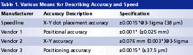
Typically, dispensing platforms specify only x-y repeatability or dot placement accuracy (expressed as a Sigma value). These specifications fail to cover all the error mechanisms associated with the true accuracy and repeatability of a given platform.
The Evolution of GantryGantry and drive mechanisms are the preeminent aspect of a dispenser design, and are critical to ensuring the overall platform’s performance and stability. Early designs used a welded steel frame mounted with a cable driven gantry and stepper motor drives. Stepper motors were later replaced by servo drives and linear encoders, which improved accuracy and speed but lacked high-speed rigidity and attainable accuracy. In a parallel move, cable drives were replaced by DC servo motors that drove a ball or lead screw mechanism. Generally, these gave somewhat better long-term performance and positional accuracy, but had speed limits. By the mid-1990s, linear drive technology designs led to the development of third-generation gantry designs (Figure 1a).
The benefits of linear drives are immense. Preloads are minimal as physical restrictions imposed by screw and bearing assemblies are eliminated; accelerations and speeds are nearly double that of previous designs. A range of available motion control packages enables selection of state-of-the-art electronics to further enhance performance. Pivotal to the drive mechanism are the drive electronics, motion controller and interface. A common approach for motion controller design is to mount the card(s) into a PCI slot within the PC, connecting through cables to a backplane, then to the axis amplifiers and finally taking those signals out through the backplane to the motors. Changing to an Ethernet-based scheme permitted the motion controller to mount directly to the backplane, giving direct connection of all I/O, encoder and motor feeds. This reduces internal cabling and cost, and raises communication speeds. Raising the bus voltage to 75 VDC permits the motors to run at much higher speeds. The motors in turn are controlled by the latest digital signal processor motor amplifiers, permitting higher gains in current, velocity and position loops. Velocity loop tuning is shared by the drive and controller for broader damping and reduced settling times. Combining polymer gantry architecture with these innovative control techniques provides a drive mechanism that is extremely accurate, exceptionally fast and well able to realize long-term, repeatable performance in real-world manufacturing environments. |
Many factors influence positional accuracy, including x-y gantry design (sidebar), drive electronics, motion controllers, vision system, camera calibration, camera-to-needle offset calculations and even the dispense pump or valve used. Different modes of operation can affect accuracy, and each should be associated with a separate specification. For example, a jetting technology would show differences in capability when the valve is in continuous dispense mode versus when the valve settles before dispensing. This would also be apparent if a high-resolution mode is used.
Current accuracy specifications tend toward the general, vague and inconclusive. They rarely give a solid feel for what platforms are capable of or how tests are run. They are of limited value when users attempt to qualify and compare different machine specifications (Table 1). The specifications shown refer to some type of accuracy, but it is impossible to draw a quantitative conclusion as to how they compare, or what qualities are actually being referred to. The data and descriptions are quoted directly from various dispensing equipment vendors.
Gray areas abound:
Does dispensing of actual material occur during tests? If not, how are they tested?
Are specifications at 3-Sigma or 1-Sigma when not otherwise stated?
Is there a difference between positional accuracy and x-y accuracy?
Are tests run at full system speed?
Is a machine vision system used?
To clearly determine a given platform’s capability, a new test method needed to be developed. Such a measurement should consider all influencing factors and express them as CpK around stated specification limits. (Note: A measurement specification stated at 3-Sigma represents CpK >1.0.) A new metric calculates the total system accuracy (TSA) of a dispensing platform.
TSA measurements are taken from dispensed material on a substrate relative to a defined target. An array of dots are dispensed at full system speed relative to circular fiducials. Full system speed indicates the standard x-y-z speeds and accelerations used in a high-speed production environment.
Material buildup at the tip or orifice tends to degrade accuracy. As such, we recommend a series of tests be run and averaged. The dispense flow or jet will deflect from target due to uneven surface tension at the release point. The deviation in accuracy is proportional to the release height of the fluid from the substrate and the material’s velocity approaching the substrate. Ballistic jet technology shows a more adverse deviation than needle dispensing in this condition, and requires more periodic cleaning to remove material and effectively counter positional deflection.
We used an independent third party to verify our test results. This ensured the methodology was correct and the system would perform to expectations during normal production use. The data below represent the average from a series of such tests. Platform performance should always be less than the stated limits. Result: The TSA of the studied platform is 50 µm @ 3-Sigma.
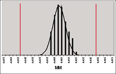 FIGURE 1: Bell curve specification limits. |
The data in Figure 1 show a CpK of 1.91 at those limits. Again, this datum represents an average of multiple tests.
Using a system with twice the accuracy of standard platforms, applications with tight gaps that require pinpoint positioning of the needle between components can now realize dispensing at even faster speeds. Needles still have the advantage when dispensing in areas tightly packed with tall devices – an application that can pose interference issues with jet and other needle-less technologies.
Dispensing speed for any system is always application-dependent. Trials will typically be run by the vendor to determine throughput on a customer’s actual product. Throughput for SMT dot applications can be judged by using equipment manufacturers’ stated specifications in dph. This indicates whether the dispensing system is suited to low-, medium- or high-volume production; high-end platforms dispense at >35,000 dph.
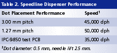
As is the case with accuracy, dot placement rates require a better standard. IPC-98501 provides an excellent solution and can be easily run on any system. (For its equipment, Speedline states a gross placement speed and IPC-9850 results.) The test board described in IPC-9850 contains 400 components offset at various pitches. Dispensed dots are surface-mount adhesive, 0.5 mm in diameter and dispensed with a 2.5 mm lift height. Final speed test result (Table 2): The new platform increases the dispense speed on the IPC-9850 board to 35,000 dph from 25,000 dph, an improvement of 40%.
Small Dot Deposits
“MicroDot” is a dispensing term used for applications that require a repeatable deposit of material <250 µm in diameter. Challenges in dispensing such small amounts of material include z-axis accuracy, speed and a suitably repeatable dispensing medium. Servo-driven auger screws have usually proved the most effective dispense means. These permit a resolution up to 75,000 increments per revolution, precisely metering dispense diameters down to 150 µm.
Other critical factors include driving the needle to the correct distance from the substrate and maintaining that distance. The dispense height for dots can be as low as 20 µm, so minimizing z-axis overshoot is key. Where applications permit, one common technique employs a needle with an attached standoff or foot. This sets a fixed distance from the needle tip, so when in contact with the substrate the dispense gap remains consistent. Though effective, its practicality can be limited. Certain substrates may be damaged due to foot impingement. In higher density applications the foot may interfere with surrounding components.
One complete solution might be a noncontact method of dispensing. Jetting is a fast alternative, but its ballistic technology is limited to dot sizes of >330 µm and its results are not repeatable with all materials.
Footless needle dispensing can provide the repeatability needed, but to attain height consistency the system cannot overshoot. Generally, overshoot is eliminated by running the z-axis very slowly, either for the full stroke or the last part of the down stroke. Efficient in most cases, but time-consuming.
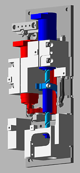 FIGURE 2: Direct z-axis drive in which the motor and precision ball screw drive are directly coupled. |
Figure 2 shows a edesigned z-axis in which the motor and precision ball screw drive are directly coupled. This significantly reduces inertia and friction, helping eliminate overshoot and decrease settling times. Result: a 25% increase in z-speed and reduction of overshoot tenfold to <5 µm.
An established technology such as needle dispensing can often be dramatically improved. Be sure to take into account the positional accuracy of the dispense mechanism versus physical limitations or restrictions in other employed technologies. Underfill material is dispensed relative to component or die edges. Therefore, the best positional accuracy is achieved by dispensing in reference to those edges. With the novel system, for example, refined machine vision algorithms permit a one-snap process that simultaneously finds all four edges of a package, ensuring the positioning (Figure 3). The software maps the edge transition of the image and calculates the best line; this permits the needle to run parallel to all four sides, even when the edges or corners are uneven and chipped.
| FIGURE 3: Improved software simultaneously finds the four edges of a package, ensuring accurate positioning (click here to see image). |
Needle dispensing of underfill does require height sensing. With the new platform, this is done in a batch mode with the vision system prior to material dispense; sensing determines the top surface position of the substrate to which the system positions the needle. Lasers scan the product, stopping momentarily for sampling. On average, laser sampling takes approximately 0.3 sec. per site, including x-y travel. In general this approach is used more often than mechanical probes, which take 2 sec. per site.
At one customer’s Asian operations, extensive underfill testing showed cycle time improvements in all associated processes. Figure 4 is a breakdown of cycle time improvements for the two-pass underfill application. These improvements can in part be attributed to the system’s new sequence command, which maintains pump and gantry speed around corners, giving a faster and more consistent dispense line and eliminating corner balling.
| FIGURE 4: Cycle time comparisons show a 42% overall improvement using the new gantry drive (click here to see image). |
Measuring Conclusions
For optimum dispensing system success, the gantry mechanism is key to positional accuracy, speed and long-term performance. Advanced drive electronics and motion controllers only benefit a gantry that is up to its task in all other respects; they cannot compensate for an inadequate structural design. Also, the repeatability of any dispense pump or valve is heavily reliant on how well it is positioned.
For users to fully evaluate the capability of equipment, speed and accuracy specifications must reflect real-world conditions, not just best-case scenarios. We need new specifications for both elements. Accuracy should have a stated specification of dispensed material to fiducials at full system speed; we propose TSA as this metric. Speed or dph should be measured in reference to a known standard; we suggest adopting IPC-9850. n
References
IPC-9850, Surface Mount Placement Equipment Characterization, October 2002.
Hugh Read is product manager, Camalot Dispensing Products, Speedline Technologies (speedlinetech.com); hread@speedlinetech.com.


Press Releases
- XLR8 EMS Welcomes Raul Jorge Lopez Jr. as Director of Program Management and Procurement
- Koh Young America Promotes Ramiro Mora to Lead Service and Applications in Mexico and South America
- ViTrox Americas Welcomes Huy Pham as Technical Support Engineer
- XLR8 EMS Appoints Steve Dutton as Chief Sales Officer