

2005 Articles
A Novel IR Rework System
Oynamic temperature control and sensors help manage heat in Pb-free processes.
The goal of 100% first-pass yield remains in the praxis unachievable. The smaller process windows and higher process temperatures associated with Pb-free have complicated the matter. The risk of overheating adjacent or bottom-side components during rework is greatly increased. As the cost per PCB increases, it becomes more important to reduce both the scrap rate and returns caused by improper rework.
An analysis of the most important system requirements is a valuable aid in selecting appropriate rework technology. The four most important system requirements to consider for a SMT/BGA rework system designed for Pb-free are:
1. Does the heating technology provide for uniform, intelligent heat distribution?
What is the delta temperature (dT) across the component in the selective reflow zone?
What is the dT across the entire PCB during the process?
What is the dT between the top of the component and the bottom of the PCB?
Is the heating system dynamically controlled with respect to the optimal energy input from the top and bottom?
Does the system permit a flat peak as required to compensate for PCB-specific dTs across the component land array?
2. Does the heating system provide sufficient top and bottom heating size and power for Pb-free applications?
Is the heating system capable of achieving a proper temperature gradient and profile, even on large and heavy multilayer PCBs?
Can the selective reflow system preheat the entire PCB from top and bottom in such a manner as to prevent excessive PCB warpage during rework?
3. Does the true component or PCB temperature dynamically control the heating system during reflow?
Are sensors used not only to monitor component or PCB temperature, but also to actively affect heater output during the process?
Can multiple sensors, noncontact IR and low mass K-type, be used to drive the heating system in a “true closed loop” control?
4. Given higher Pb-free working temperatures and smaller process windows, which safety features are incorporated in the heating system to prevent the component, adjacent components or the PCB from overheating?
Can the sensors placed on the PCB dynamically control and reduce the power of the heating elements if a prescribed limit or threshold temperature value is approached?
Can these sensors be placed in multiple locations anywhere on the PCB or on critical temperature-sensitive components? Can all sensors be assigned different temperature limit values; and can any and all of these sensors actively affect the heaters during the process?
True temperature control on the board and component is the ultimate goal in rework (Figure 1). The rework system must compensate for the different masses of the component and PCB in order to keep dT to a minimum. A new novel automatic rework system uses medium wavelength infrared heating technology for uniform heat distribution from the top- and bottom-side across the PCB and component. It has fully automatic dynamic control of the top (1400W / 60 x 120 mm) and bottom (3200W / 350 x 450 mm) IR heaters, depending on the actual temperature of the component and where it is in the temperature profile. The total available power (4600W) to the selective reflow system is spread across four separately switchable heating zones on the top and five zones on the bottom. Attributes such as board size, thermal mass of the substrate and the component size are taken into account when establishing the temperature profile. This lowers the dTs across the component and reduces PCB warpage (Figure 2).
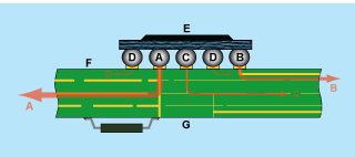 FIGURE 1: Solder joints (A, B, C, D) must be taken to proper peak temperature while keeping to a minimum dT between the component body (E) and substrate top and bottom (F and G).
 |
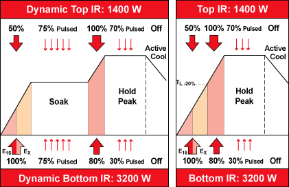 FIGURE 2: The dynamic IR heating principle adjusts heating energy based on board size, substrate thermal mass and component size.
 |
The system also incorporates “true closed loop control,” which means that the actual component temperature is acquired using a patented IRS noncontact IR sensor, and is used as the primary control mechanism for the heating system. This permits a more precise temperature measurement by choosing from a component table or component-specific IRS calibration. The system uses either an IRS or K-type NiCrNi TC sensor to drive the heating technology, to ensure a repeatable profile. As many as four additional sensors can be added. By assigning threshold values to these additional sensors, they are used to prevent the heating system from overheating adjacent or bottom-side components. The heating system automatically reduces or increases energy to the top and bottom IR heaters to guarantee that a set threshold temperature is not exceeded (Figure 3).
 FIGURE 3: Up to five sensors ensure maximum allowable temperatures are not exceeded.
 |
Mark Cannon is president and COO, ERSA GmbH (ersa.de); mark.cannon@ersa.de.


Press Releases
- Altus Group Invests in Major Headquarters Expansion to Showcase Complete Turnkey Manufacturing Capability
- ViTrox Americas Welcomes Eric Cruz as Technical Support Engineer
- ECD Strengthens Engineering Team with New Software Development Hire
- ViTrox Americas Welcomes Doug Ennis as Senior Field Applications & Service Engineer