

Optimized Materials to Deliver Ruggedized Electronics
A showcase of testing methods used in the development of robust materials.
Ruggedization means “to strengthen (something, such as a machine) for better resistance to wear, stress, and abuse.”1 Automotive systems are built for aggressive environments and are categorized as ruggedized electronics. One usually thinks of an all-terrain vehicle navigating an uneven landscape in an extreme hot or extreme cold environment. The systems require more robust electronic hardware due to their unusual working conditions and environmental exposure.
Today’s automotive electronics, specifically those for advanced safety features, require ruggedization against traditional as well as additional self-inflicted abuse. The high level of processing required to execute “sense” and “respond” of multiple safety systems working in concert creates increased heat and increased mechanical strain leading to shorter characteristic life. Advanced IC substrate packages create challenges for the system as well. The need to combat these additional challenges requires specific ruggedization. This work will discuss material choices that were designed to combat temperature, vibration, heat, and various aggressive environments to offer extended system life.
The authors’ purpose is to showcase test methods used in the development of robust materials. The work will bring attention to automotive specifications such as IPC-6012DA2 but will focus on the value of material specific testing to inform us on properties and enhancements on the path to system-level testing. Predicting the needs of many different safety systems across the industry for a wide range of design criteria is impossible. The development work brings insight to the steps taken to create materials with wide operating windows that address a range of needs in the automotive space.
Materials for multiple levels of the electronics build are reviewed including printed circuit board (PCB) surface finish, solder paste alloys, assembly adhesives, and conformal coatings. Testing includes solder joint reliability, vibration exposure, surface insulation resistance, and exposure to condensing environments.
Two major trends are responsible for growth and performance changes in automotive electronics. They include the transition to an electric powertrain and the journey to autonomous vehicles. Both megatrends require more robust electronics. Electrification requires high-power electronics that can compensate for high temperatures. High-speed and high-processing power advanced safety also requires the ability to withstand temperature fluctuations and mechanical stresses connected to coefficient of thermal expansion (CTE) mismatch. Finally, consideration for aggressive environments including high temperature, dirt, dust, and even condensing environments has always been a necessity.
A widely used surface finish for high-reliability applications is electroless nickel/immersion gold (ENIG). End-users prefer this finish for extended shelf-life preassembly and its resistance to the environment in final application. Although known for its corrosion resistance, the chemical nature of plating gold on nickel requires corrosion to occur. It is an exchange reaction that happens when nickel is removed from the surface for gold to plate. A risk with this process is uncontrolled corrosion during plating that can lead to a defect called black pad or black line nickel. This shows itself only after assembly when a proper solder joint is not created, and the electrical connection can be compromised by a crack or complete fracture of that solder joint.
IPC-4552B defines cross-sectional analysis to understand corrosion of the nickel layer in advance of assembly.3 It can save an assembler or end-user time and money by detecting a potential defect in advance of assembling expensive components. Our development team has used cross-section as well as gold stripping and scanning electron microscopy (SEM) analysis to characterize corrosion of the nickel in combination with gold plating. These methods help determine which process and formulation adjustments can be made to achieve better resistance. Yet, all these methods focus on a spot location and do not always reveal the true performance of the finished PCB.
A more practical tool is ball shear testing. This solder joint reliability test can be executed faster and delivers tangible information on a larger scale when compared to cross-section or SEM. Analyzing shear force and the resultant failure mode delivers more realistic information about performance than a spot view of a corrosion spike.
For the evaluation of two ENIG processes, a test board containing an 84-count BGA design with solder mask-defined pads was used. The pad opening was 600µm. After ENIG plating, solder paste was printed, and solder spheres were placed using a small stencil on the ball grid array (BGA). After reflow, shear force was measured using a Xyztec Condor 70 tester at 0.35mm/sec. Parts were measured for shear force in Kg, then failure mode was analyzed optically. Only two failure modes resulted, die shear and die break. Die break (Figure 1), the preferred failure mechanism, happens within the bulk solder. This indicates strong interface bonds. A die shear (Figure 2) failure mechanism indicates weak bond strength between the solder and pad finish.
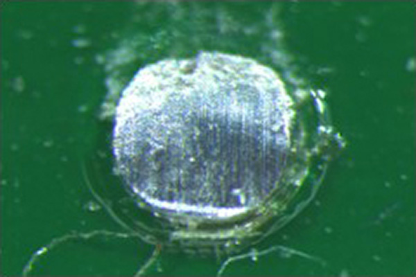
Figure 1. Die break is a failure which happens within the bulk solder.
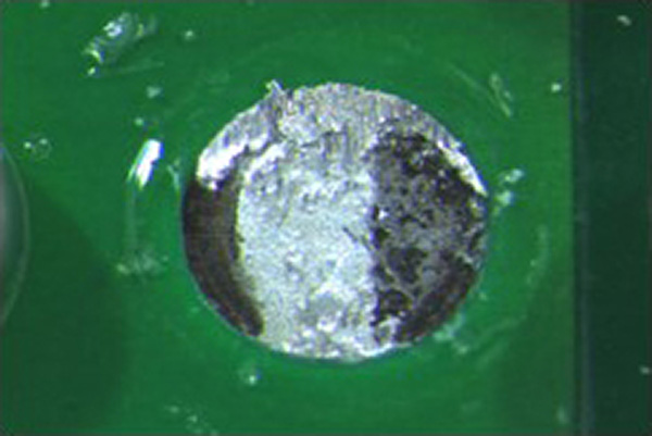
Figure 2. A die shear failure indicates weak bond strength between the solder and pad finish.
Two ENIG systems were tested to gain a deeper understanding of corrosion performance. A market-leading ENIG was tested against an optimized ENIG process. Both processes contain medium phosphorus electroless nickel plating systems. A textbook understanding of phosphorus ranges would put these systems between 5 and 9%. By optimizing the type and concentration of stabilizer in the electroless nickel bath, a process can deliver a more consistent phosphorus content throughout the bath life. This was the desire of the development team. By controlling the phosphorus content within a narrower window than convention, the bath would naturally eliminate swings in the corrosion created during plating. Eliminating swings in the phosphorus was expected to significantly reduce excessive corrosion and that result was in fact delivered.
Both ENIG systems passed the required shear force of 1.5Kg but the optimized ENIG process displayed a higher average force with lower standard deviation (Figure 3). More importantly, the optimized ENIG only delivered die break failure modes (Figure 4). No die shear failures were observed.
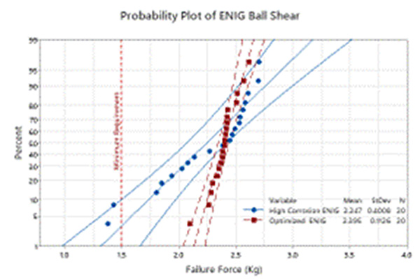
Figure 3. A Weibull plot of shear force in kilograms.
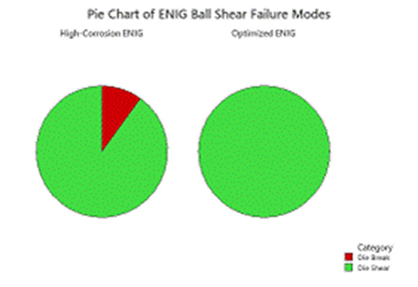
Figure 4. Ball shear failure modes.
A reliable surface finish is one of the first steps in delivering a successful system. The next in an electronics build is the solder joint reliability.
When evaluating solder paste alloys, mechanical resistance is an area of strong interest. In automotive applications, vibration resilience is important for system success. Most industry standards exist to test the full system but as a material supplier it is critical to test the paste alone in development on the path to understanding interactions in a system. The purpose of this experiment was to design a test regime suitable for differentiating the vibration performance of similar solder alloy formulations.
A 119mm2 by 8mm-thick printed circuit board with 1oz. copper traces was designed for vibration testing. The thin, flexible, lightweight nature of the test vehicle permitted more movement during the test. All copper pads were solder mask-defined (SMD) to concentrate vibration stress at the solder meniscus/mask/board interface.
Three components were selected for analysis: PBGA256 dummies with 1mm pitch and SAC 305 spheres and two types of resistors, 1206 and 2010 (Figure 5). PBGA256 were specifically selected for their relatively large body size, 17x17mm, to maximize potential deflection during vibration. Copper test points were added to isolate the failure site post-vibration. The 1206 resistors were added to deliver more typical board conditions where passives surround the BGA. This would permit a more comparable strain rate. They were also added to conduct shear testing. The 2010 resistors were used as visual indicators.5
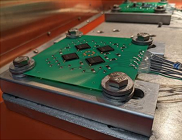
Figure 5. PBGA256 dummies with 1mm pitch and SAC 305 spheres and two types of resistors, 1206 and 2010, were used for analysis.
Paste was printed on the board with a 5-mil stencil and 500µm BGA apertures (40% area overprint). The final mixed solder joint is 2:3 paste to ball by volume. A no-clean flux was used for each of the three alloy pastes, and the boards were not cleaned before testing. The effect of flux residue on vibration resilience is assumed to be negligible.
Most vibration tests call for an electrodynamic shaker, but for this experiment a repetitive shock (RS) chamber was used. In a repetitive shock chamber, only the amplitude of vibration can be controlled, not its frequency profile. Most existing research and automotive standards use electrodynamic shakers, so any results taken from this experiment cannot be directly compared to the results of those tests. The random spectrum defined in ISO16750-3 was used as a target, it delivers a total of 18.4gRMS at frequencies ranging from 10Hz to 2kHz.5
The test was executed to compare three similar solder alloys; the traditional SAC alloy, Alloy A designed to achieve enhanced thermal cycle resistance, and Alloy B, a next-generation high-reliability alloy designed to improve mechanical performance. Alloy B is a SAC-based alloying solution with additions to improve strength and optimize microstructure to inhibit crack propagation. Alloy B reflows at traditional SMT reflow profiles of approximately 245°C peak temperature.
This test also included the addition of a polymer reinforcement on the BGA packages. It was designed to understand the influence of an integrated solution and how that would affect system-level performance.
The Weibull plots indicate that Alloy B outperformed Alloy A and SAC 305 in vibration resilience (Figure 6). By developing a solder paste focused test, fine differences in the solder alloys can be evaluated. The addition of the edge bond polymer reinforcement completely mitigated any failures, and we were unable to generate a Weibull plot for this condition.
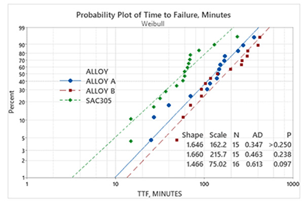
Figure 6. A Weibull plot of time to failure.
In the continuously changing landscape of advanced safety, automotive designers have quickly transitioned to advanced packages to achieve desired function. The use of BGA-style packages is changing the capabilities of vehicles today. They deliver huge advantages, but they are a significant concern for the industrialization teams at each automotive T1 and OEM. The use of enhanced reliability solder alloys has been widely adopted in the advanced safety system space. As seen above, they improve vibration performance and a host of data support their resistance to thermal cycling.
Depending on package type, size, PCB layer count and build, in some instances a polymeric adhesive is the proper choice for a particular design. During temperature cycling the package moves differently than the circuit board, often flexing at the edges of the package. This is the result of a CTE mismatch. This puts more mechanical pressure on the outer solder spheres. It can result in fracturing of a sphere. To further support the package, a design may use a polymeric adhesive. Many designers resist use of an underfill because it is difficult to rework or has a negative impact on radio frequency properties. A great alternative is a corner or edge bond, which delivers structural rigidity without touching the solder spheres.6 Pay attention to the potential chemical interactions of solder flux under the package and polymer adhesive. This is especially true for low-profile packages.
This particular test method offers further insight into interactions between the polymer adhesive and flux chemistry. In accordance with IPC J-STD-004A, B-24 comb patterns were printed with solder paste and reflowed in a BTU Pyramax 125N oven. Edge bond materials were printed over bare coupon as a control and over solder paste test coupons to deliver complete covering of the combs. Coupons were then cured in a convection oven as per the polymeric adhesive recommended procedure.
Coupons were conditioned during testing using an ESPEC temperature humidity chamber. To deliver more harsh conditions, the temperature was run at 85°C and 85%RH under a 50V bias. These conditions are normally more challenging for the edge bond materials. Surface insulation resistance (SIR) measurements were made using Gen3 AutoSIR or AutoSIR2 SIR dataloggers. To add complexity, the test was extended to 1000 hr., a significant increase over the IPC-J-STD-004A test of seven days, to represent typical automotive testing conditions and ensure any solder paste and polymer chemical interactions would be effectively evaluated. Also note, an internally developed test methodology was used to represent the environment of a low-standoff package.
Careful consideration should be made when selecting a polymer solution as an ineffective cure condition could lead to incompatibility with the solder paste flux chemistry, potentially leading to electrochemical migration. Figures 7 and 8 show that the proper choice of materials will result in desired surface insulation resistance and no presence of dendritic growth.
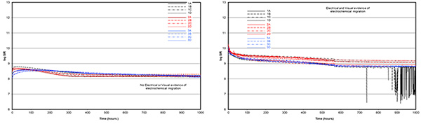
Figure 7. SIR data from testing.

Figure 8. Optical observation of failure modes.
The review on ENIG and the solder paste alloys was designed to formulate improved materials. The above test informs on synergies or incompatibilities to educate assemblers on their process materials. It will save time and resources when trying to choose a polymeric material for advanced package assembly that works with an approved solder flux chemistry.
Finally, there are instances when the critical nature of electronics will not permit even the slightest chance of failure. In this instance, full protection of the assembled PCB from condensation, particulate, and any foreign material may be required. In this instance a conformal coating would be used.
Most designers in any industry will tell you they do not use conformal coatings. Prismark Partners, however, estimates that conformal coatings was a $350 million market in 2021 and almost 50% of the segment is dedicated to the automotive industry.7 This protective coating is designed to conform to the contours of the assembled board to deliver protection and extend product life.
In line with the previous test, high processing of advanced safety electronics for full autonomy generates exceptional amounts of heat. The possibility of localized condensation is a concern for many, especially under low profile packages. Also, these advanced processing packages need to deliver information quickly. They are fine-pitch components. A moisture barrier such as a conformal coat can prevent localized condensation from creating a pathway for electrochemical migration.
A well-known issue for conformal coatings called sharp edge coverage is its ability to cover device leads completely and reliably. Thin or missing coverage of solder joints and other metal surfaces make them susceptible to corrosion in a long-standing corrosive or condensing environment (Figure 9). This issue was recently highlighted by the J-STD-001 Conformal Coating Material & Application Industry Assessment (5-22arr).
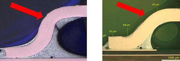
Figure 9. Sharp edge coverage (poor, left, and complete, right).
A new generation of 2K (two component) conformal coatings was developed to be applied thicker and to resist poor sharp edge coverage. It was designed to deliver greater moisture and thermal resistance than its acrylic counterparts which have limitations in the thickness they can achieve.
An internally designed test coupon for assessing conformal coating performance was used. It includes multiple package types; BGA, SOIC and a comb pattern. The boards were populated then coated with various test formulations. Solvent-based formulations were coated to a dry-film thickness of 50µm while the solvent-free material was coated to 30µm. All samples were cured at room temperature for seven days. To increase the intensity, this test ensures condensation representing a more aggressive test than humidity. It reveals performance information closer to immersion. Samples were tested using an AutoSIR2+ climatic chamber at 40°C (104°F)/93%RH under 50V bias for 10 hr. Parts were cooled to 36°C (97°F) and heated up to 40°C (104°F), using a 20 min. cycle time.
Optical analysis of the SOICs showed that the uncoated control and acrylic-coated parts revealed high variations in insulation (Figure 10). Both the uncoated board and acrylic-coated board fell below the required resistance of 1×10⁸Ω. This was observed when the temperature dropped below the dew point and water droplets formed on the board. The 2K material displayed better condensation protection and kept a consistent resistance during the cycle testing. It was able to remain well above the required 1×10⁸Ω.
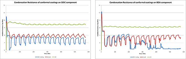
Figure 10. Insulation resistance charts.
Analysis of the BGA packages reveals a different scenario based on the package shape and low profile. During this intensity of testing, water can get under the BGA but will not dry or fully evaporate with time. That potential became clear and showed itself for the uncoated board. The moisture caused it to fail; resistance was completely lost. The acrylic coating resulted in improved protection but did not achieve the desired result.
This is a very harsh test for a solvent-based coating compared to traditional humidity testing. Again, the 2K material showed good protection above the required 1×10⁸Ω with minimal changes during each cycle throughout the testing time.
Conclusions
The necessity to create more robust electronics specifically in the automotive space stems from the harsh working conditions of a vehicle, but present designs created for advanced safety and connectivity create an additional challenge caused by high processing. Careful consideration should be taken for all material inputs during the design phase to ensure system-level reliability is achieved for ruggedized electronic devices. Understanding performance criteria and design is critical for success. Chemical and material suppliers need to take a different view of reliability testing to qualify materials in their individual state. Learning from this testing informs us on formulation and process changes that will offer end users a wider operating window with improved performance.
In some instances, it is necessary to break from an industry standard for additional information or to find finer differences. By developing in this way, we not only deliver better products but can also make informed recommendations for specific builds.
It is important to seek enhanced materials in this ever-changing automotive segment.
Ed.: This article was originally published in the proceedings of the SMTA Electronics in Harsh Environments Conference 2023 and is republished here with permission of the authors.
References
- Merriam-Webster Dictionary.
- IPC-6012DA, “Automotive Applications Addendum to IPC-6012D Qualification and Performance Specification for Rigid Printed Boards,” December 2018.
- IPC-4552, “Specification for Electroless Nickel/ Immersion Gold (ENIG) Plating for Printed Circuit Boards,” August 2017.
- JEDEC JESD22-B117B, “Solder Ball Shear,” September 2020.
- Fox, Kennedy, et. al., “Highly Accelerated Vibration Testing for the Evaluation of Solder Alloys in Automotive Applications.” IPC Apex, January 2023.
- Jimmy Shu, “Edge Bonding AS Viable Reinforcement for Solder Joints in High Reliability Applications,” SMTA International, November 2021.
- Prismark Partners LLC.
- Thomas Koschmieder, Ph.D., “Board-Level Reliability Test Method and the Automotive Electronics Council,” SMTA International Oct. 31-Nov. 2, 2022.
- F. Kraemer, K. Meier and S. Wiese, “The Influence of Strain-Rate Dependent Solder Material Models on the Interconnection Stress of BGA Components in JEDEC Drop Test,” 4th Electronic System-Integration Technology Conference, September 2012.
is director of Autonomous Driving and Safety at MacDermid Alpha Electronics Solutions (macdermidalpha.com); lenora.clark@macdermidalpha.com; is director of SMT & Preforms Circuit Board Assembly; is director of Final Finishes Circuitry Solutions; and is global product manager of Conformal Coatings


Press Releases
- Javad EMS Upgrades Through-Hole Soldering Capacity with New SEHO PowerWave System
- Sharpen Your Selective Soldering Skills with Kurtz Ersa's July VERSAFLOW 4/55 Training
- Omron Advances Inspection Technology with NVIDIA Omniverse and Metropolis
- Seika Machinery’s SMI 2026 Webinar Series Continues with Focus on PCB Cleaning Before Solder Paste Printing