

Vibration Resistance and Durability of Wirebond for EV Batteries
Mitigation techniques to eliminate wire breakage failures.
Wirebond technology has long been used in semiconductor manufacturing because of its inherent flexibility, considered a major advantage as an interconnect method. With wirebonding, electrical interconnections or wirebonds are created between the silicon die and its leadframe or substrate using fine bonding wires made of gold, aluminum, copper, silver alloys or palladium-coated copper composites. These wirebonds are delicate though flexible, and in semiconductors, are usually encapsulated by buffer materials such as resin or mold compounds, giving them a measure of durability and the ability to resist damage from vibration. That measure of durability is lost in open-air applications, however, including EV battery packs where there is no molding or encapsulation material to protect the wirebond from the effects of vibration.
Here, the authors look at ultrasonic wirebonding as currently used for interconnecting cylindrical lithium-ion (Li-ion) cells in EV battery packs, where such wirebonds are vulnerable to breakage due to vibration in part because they are not encapsulated. Also reviewed are vibration tests of wirebonds using a) test equipment developed for this study, and b) five types of comparison studies (vibration direction, material, wire shape, loop height, single bond or wirebond).
Ultrasonic wirebonding is currently used for the interconnection of cylindrical Li-ion cells in EV battery packs. The negative wire is bonded to the cell rim while the positive wire is bonded to the cell center cathode, which is supported by thin legs that are prone to vibration. The cell can is made of nickel-plated steel with the crimped rim having rounded cross-sections. Wirebonds are designed for flat surfaces, and bonding on the rounded cell rim makes it even more challenging. The cell rim surface roughness is also inconsistent due to the crimping process and is prone to corrosion and electrolyte contamination.
Rough road conditions, rough handling or sudden acceleration/deceleration of the EV could cause wire fatigue and eventual breakage due to vibrations generated under such conditions. The result can be breakage at the neck region between the bond and the span of the wirebond, a common cause of energy capacity loss in EV battery packs.
The goal of this study was to analyze the wire breakage problem and to offer mitigation solutions to reduce or eliminate the failure.
Setup
Vibration tests were performed using in-house designed test equipment composed of a vibration generator, tables and automatic timer installed in a clean room, with temperature set around 20°C and humidity around 50% RH.
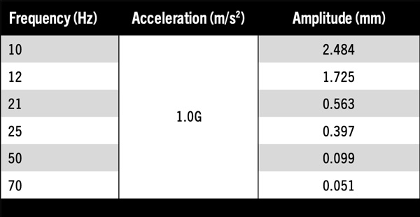
For the vibration, given a constant acceleration of 1.0G, the test vibration frequency was varied from 10-70Hz, providing inversely proportional amplitudes as listed in Table 1. One table is vibrated while the other is stationary. The automatic timer is wired such that it stops on the occurrence of wire breakage.
A = (2πf)2 x D/1000 (m/s2)
where
A = Acceleration (m/s2)
D = Amplitude (mm)
F = Frequency (Hz)
Table 1. Vibration Frequency vs. Amplitude
Using a high-speed camera, crack propagation and wire breaks were recorded during the tests. As expected, cracks are initiated in proportion and direction to the vibration. For example, in the vertical vibration test where the top motion is longer than the bottom motion with respect to the original plane of the vibrated bond, a crack initiates from the top portion of wire first. This is followed by a bottom crack directly opposite it. Both cracks progress toward each other across the cross-section of the wire until rupture. Figure 1 shows a SEM image of a typical wire break.
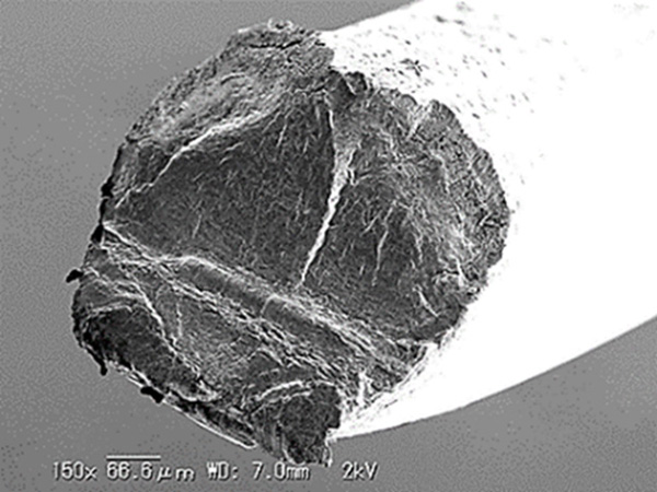
Figure 1. Typical wire break. Note rupture line near center.
Figure 2 shows the test wires made with either 20mm long wire or ribbon bonds spanning two aluminum plates spaced 5mm apart. The first bond side is stationary, and the second bond side subjected to vibration during testing.
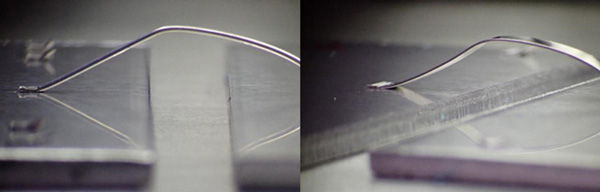
Figure 2. Round wires used in the study are 400µm in diameter (L) while the ribbons measure 2000µm x 200µm (R).
Results
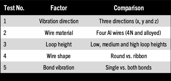
The test conditions were designed to help understand the most significant factors that might contribute to broken wires in EV applications. The study consists of five tests composed of various factors as listed in Table 2. Three vibration axes (x, y, z), four types of aluminum wires, three loop heights, two wire shapes (round vs ribbon) were tested. The final test compared the performance of one bond vs. one wire vibration.
Table 2. Factors Used in the Study
Test 1: Vibration direction. The first set of tests was for the vibration of the second bond, with the first bond being stationary, in x, y or z axes with respect to the wirebond length using 400µm diameter Al wires.
As shown in Figure 3, in the x direction test where the wirebond is basically stretched, there is a high incidence of failure. This is akin to a tensile stress of the wirebond and the weakest link in this case, the neck region of the vibrated second bond, typically ruptured after at least a thousand cycles.
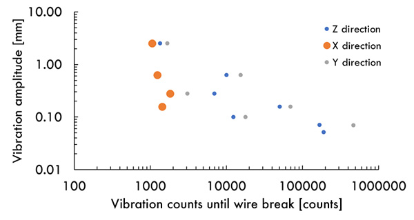
Figure 3. Wire breakage vs. vibration axes.
For the y direction where the second bond is vibrated from side to side with respect to the first bond, failures varied from 1,000 up to 1 million cycles. Surprisingly, the same failure rate was observed during the z direction vibration, where the second bond is vibrated up and down with respect to the first bond.
Test 2: Wire material. In the second test, four aluminum materials made in 400µm diameters with various tensile strength and electrical conductivity were compared as listed in Table 3.
Table 3. Aluminum Materials Tested
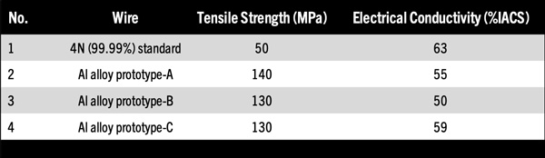
The results shown in Figure 4 show no significant difference among the wires except perhaps for Al prototype alloy no. 2 where, if the amplitude <0.1mm, improved vibration resistance was observed near 1 million cycles compared to other wires, including the standard production wire.
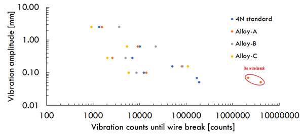
Figure 4. Wire break vs. Al material.
Test 3: Loop height. Test wirebonds were made with three loop heights: 2mm, 4mm and 8mm. As expected, the wirebond with the highest 8mm loop heights had slack that absorbed some of the vibration (Figure 5), some of which lasted up to 1 million cycles without breaking.
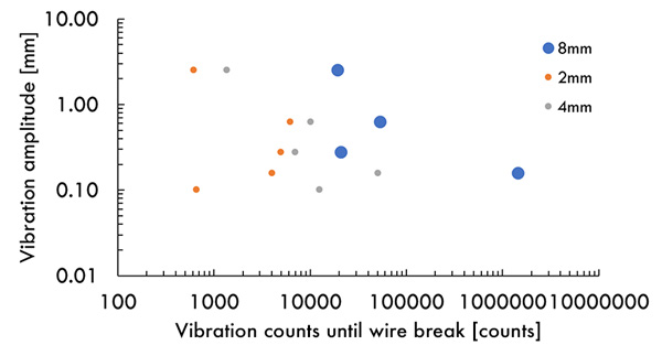
Figure 5. Wire break vs. loop height.
Test 4: Wire shape – round (400µm) vs. ribbon wire (2 x 0.2mm). Wire cross-section, either round or ribbon, was also investigated in all x, y and z axes, which resulted in significant but unsurprising results. In both z- and x-axis vibrations, the ribbon wirebond showed better vibration resistance than the round wirebond because of the former’s inherent rigidity along its cross-sectional width. In the y-axis or sideways movement, the same rigidity of ribbon wirebond worked against it, resulting in increased breakage frequency.
Test 5: Bond vibration – First bond vs. both bonds (400µm Al). The fifth test determined the vibration resistance of a single bond versus whole wirebond. As expected, wirebonds break easily when only one of the bonds is vibrated. No breakage was observed if the whole wirebond was vibrated, even for extended periods.
Conclusions
The following are findings of the study:
- Bond terminals (battery cell and busbar) rigidity with respect to wirebond are important for enhanced vibration resistance;
- Loop height is directly proportional to vibration resistance;
- Higher strength wire showed higher vibration resistance but only with amplitudes <0.1mm;
- Ribbon wires showed better resistance than round wires in x and z vibration directions.
is business development manager at Tanaka Kikinzoku International (America), Inc.; dodgie@ml.tanaka.co.jp. is a materials engineer, is an analysis engineer, is a wirebond engineer and is a materials engineer with Tanaka Denshi Kogyo K.K. (Japan).


Press Releases
- Seika Machinery’s SMI 2026 Webinar Series Continues with Focus on PCB Cleaning Before Solder Paste Printing
- Forwessun Expands Testing Capabilities through Strategic TRI Alliance
- Federal Electronics Expands Advanced Manufacturing Capabilities to Support Military and Aerospace Cable Assembly and Wire Harness Programs
- Altus Continues Irish Growth with Expansion of Engineering Team