

Stereo with Line Scan Cameras for High-Resolution 3-D Applications
With passive stereo, there are no limitations in resolution or in the type of illumination.
New technologies in production lines bring new requirements for inspection systems. One example for coming 3-D applications in semiconductor industries is inspection of small solder balls or pins used to connect wafers and dies. These components must be inspected with 3-D methods to measure the precise height of the conducting elements.
In general, the objects to be inspected are getting smaller with new technologies. At this time the typical dimensions of such components are around 5µm. Such sizes require high optical resolution of the inspection system, in the range of at least 5µm. Such small metallic objects often have partially reflective surfaces and come with the demand for high-processing speed.
Well-known 3-D approaches with resolutions in that range are triangulation methods and interferometry. There is a tradeoff between resolution and accuracy, on one hand, and processing speed on the other. Interferometry methods provide high resolution and can handle partly specular reflecting surfaces, but are relatively slow. Triangulation methods are quite fast, but slower with higher resolutions, and work best if surface reflectivity is almost diffuse.
Moving in stereo. Stereo is a common approach and widely used in combination with area cameras, e.g., for high-precision object measurements based on special markers. Stereo in combination with line scan cameras is a novel approach providing high speed and very high optical resolution, which opens new possibilities in 3-D inspection. The basic principle is the same as for area cameras: two line sensors in a stereo configuration combined in one camera.
The stereo concept is to capture two images in a so-called stereo configuration from the same object. Thus, the two stereo images show the same scene from slightly different perspectives and are the basis for triangulation: a triangle can be spanned including the object point and the two corresponding image points. If the positions of the two image points and the camera parameters are known, the distance from the camera to the object point can be calculated from this triangle (FIGURE 1).
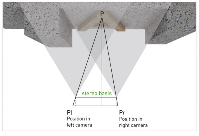
Figure 1. The stereo principle: The object point P is projected in both stereo images, denoted as Pr in the right and Pl in the left image. A triangle can be spanned including those three points, which is used for calculate the distance of point P. The stereo basis is the distance of the two optical centers of the stereo cameras.
The preconditions for stereo are:
- Only points of the object surface that are visible in both stereo images can be measured. If an object point is only visible in one image, it can be inspected in 2-D but not in 3-D.
- Finding the corresponding points. The stereo algorithm has to find the right match of the two image points that correspond to the same point on the object surface.
Active illuminations with fringe patterns or random patterns help identify corresponding image points by bringing known texture on even untextured surfaces and enhance the stability of the algorithm. With passive stereo the structure of the object surface itself is used to find the matching points. The latter approach has the advantage that there are no limitations in resolution or in the type of illumination involved by the active illumination.
The precondition for this approach is structures on the surface of the object can be resolved in the image. Two important parameters influence that: the type of illumination and the optical resolution. The illumination can be chosen in a way that fine structures show up with high contrast. The right optical resolution ensures those structures are resolved in the image.
For stereo, a standard approach to find the corresponding image points is based on pattern matching. In doing so, a small area around each point in one image is used as a pattern to be matched with the corresponding stereo image. The best match of the pattern in the corresponding image is defined as the corresponding image point. Doing this for all points (pixels) in the image results in dense 3-D data.
Unique Features of Stereo with Line Scan
The first stereo line scan cameras had optical resolutions of about 50µm, like other well-known 3-D cameras. The typical dark field line scan illumination has been used to provide high-intensity light for high speed. The advantages of those stereo cameras are speed and getting color images in combination with 3-D. Demand for higher optical resolution came next. It turned out that almost all applications requiring high resolution have partly reflective surfaces as well. To provide the right technology for those new requirements, camera makers developed high-resolution stereo cameras and bright diffuse line illuminations. Combining both – the high-resolution stereo cameras and the diffuse tube light – provides a solution for those applications. Those applications clearly show additional unique advantages of stereo cameras based on line scan:
- High resolution: Line sensors provide a large number of pixels; sensors with 7,000 to 16,000 pixels are available. This provides a large field of view (FoV) in combination with a high optical resolution. As an example, with an optical resolution of 5µm, the field of view with 7,000 pixels is 35mm.
- Flexible illumination: With passive stereo, all kinds of illuminations can be used: dark field, bright field, diffuse and co-axial light. The light conditions can be evaluated and optimized for each application. This opens up stereo for partially specular surfaces as is often not feasible with other triangulation methods. For example, FIGURE 2 shows a metal surface illuminated with dark field and with diffuse illumination. The diffuse light reduces shadows and specular reflexes and enhances the fine structures, making it possible to find corresponding points in almost every image area.
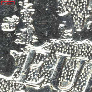

Figure 2. The type of illumination is important to reduce shadows and emphasize small surface structures. A Euro coin is shown with dark field (left) and diffuse illumination (right).
- High speed: Depending on the sensor and interface line, frequencies up to 60kHz are available. In the future even faster line sensors with higher speeds will be available. Line sensors with a large FoV and high line frequency allow inspection of a large area in a short time. For example, with 20kHz line frequency and 7,000 pixels, an area of 3,000 mm² can be inspected in one second with a resolution of 5µm. The high-speed acquisition demands for high-speed image processing requiring a lot of processing power. GPUs are primarily used now to achieve the required computational power for stereo processing.
- Fewer occlusions: If the stereo line scan camera is oriented perpendicular to the object surface, there are no occlusions in transport direction. Therefore, the occlusions are reduced in comparison to other stereo or triangulation methods with typical viewing angles of 20° or 30° with respect to the object surface.
- 2-D images in combination with 3-D: Stereo provides two gray or color images from the object, which are available for 2-D image analysis. This is a benefit if, in addition to 3-D, relevant features have to be inspected in 2-D or in color.
Application Examples
Typical applications for high-resolution stereo cameras are small objects with metallic surfaces that have to be measured precisely in height.
One application example is to measure the height and shape of small pillars used as connecting elements in semiconductor components (FIGURE 3). By using diffuse illumination, specular reflexes are avoided, and the underlying structure on the surface shows up. The images and height map are shown in Figure 3. Here, a 3-D stereo camera with 2.5µm resolution is used.
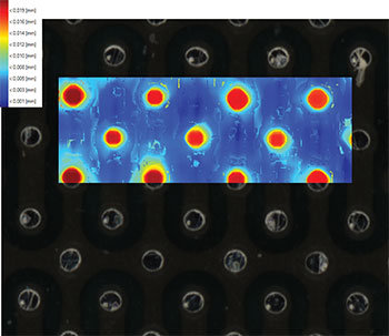
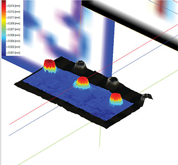
Figure 3. At left, a color image with pseudo-color overlay showing small pillars. The diameter of the pillars is 70µm. The pseudo-colors denote the height. Red is closer to the camera. The images are made with a 3-D stereo camera with 2.5µm optical resolution. At right, pseudo 3-D view of a part of the left image.
Another example is small solder joints on PCBs with partly specular reflecting surfaces (FIGURE 4). (Images are made with the novel 3-DPIXA stereo camera.)
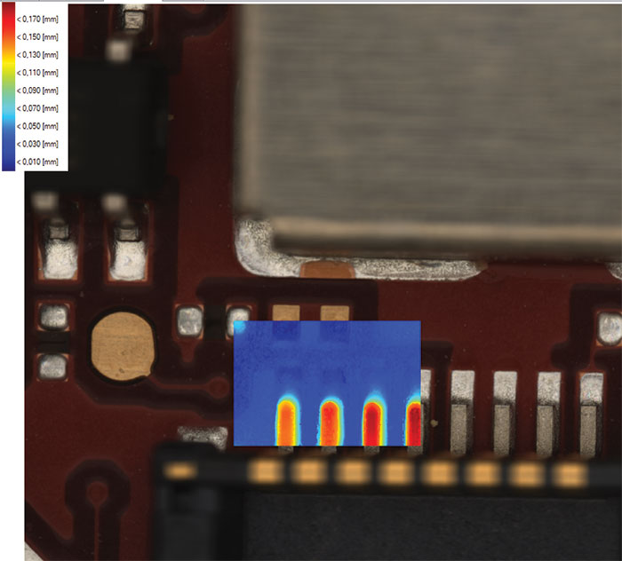
Figure 4. Color image with pseudo-color overlay showing solder joints on a PCB. The width of the solder joints is about 50µm. The pseudo-colors denote the height. Red is closer to the camera. The images are made with a 3-D stereo camera with 2.5µm optical resolution.
Inspection of wire bonds requires high resolution as well. Even with the reflective surface on the thin wires, the passive stereo approach shows the relevant details in 3-D. The right curvature is important for the functionality and reliability of the product and can be verified with this approach.
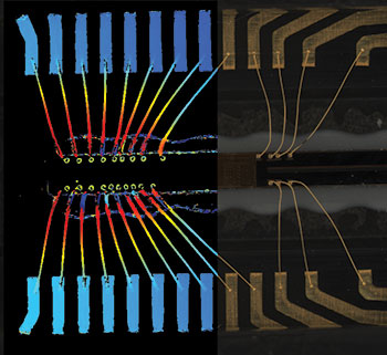
Figure 5. At left, a color image with pseudo-color overlay showing wire bonds of an imaging sensor. The width of the wires is about 3µm. The pseudo-colors denote the height. Red is closer to the camera. At right, pseudo 3-D view of a part of the left image.
Future Challenges
For most applications the stereo algorithms are running on GPUs in the PC. This requires a high-speed data interface to transfer image data from the camera to the PC, making the system quite complex. Running intelligent stereo algorithms fast on embedded hardware will permit calculations to be performed in the camera, which will make the stereo systems smaller, easier to use, and will reduce total system cost. This is an important development step toward wider use of stereo in industrial machine vision.
On the other hand, still-higher optical resolution is necessary as objects get smaller. At higher resolution, the height range becomes limited, since the depth of field is reduced with higher optical magnification. The extension of the height range of line scan stereo with new optical and camera designs will be another challenge for the future.
Klaus Riemer, Ph.D., is 3D product manager at Chromasen’s GmbH (chromasens.de); klaus.riemer@chromasens.de.


Press Releases
- Forwessun Expands Testing Capabilities through Strategic TRI Alliance
- Federal Electronics Expands Advanced Manufacturing Capabilities to Support Military and Aerospace Cable Assembly and Wire Harness Programs
- Altus Continues Irish Growth with Expansion of Engineering Team
- Kevin Castonguay Joins MicroCare as Senior Director of Marketing