

Are Current Qualification Practices Adequate?
A novel approach to predicting – and improving – device failure rates.
In the long run, we are all dead. – John Maynard Keynes
Vision without action is a daydream. Action without vision is a nightmare. – Japanese saying
Qualification testing (QT) is the major means used to make viable and promising devices into reliable and marketable products. It is well known that devices and systems pass existing QT only to fail in the field. Is this a problem? Are existing QT specifications adequate? Do industries need new approaches to qualify devices into products, and if so, could the existing QT specifications, procedures and practices be improved to the extent that, if the device or system passed QT, there is a quantifiable way to ensure the product will satisfactorily perform in the field?
At the same time, the perception exists that some products “never fail.” The very existence of such a perception could be attributed to the superfluous and unnecessary robustness of a particular product for its given application. Could it be proven that this might be indeed the case, and if so, could it be because the product is too costly for the application so intended, and therefore, the manufacturer spent too much to produce it and the customer too much to purchase it?
To answer the above questions, one has to find a consistent way to quantify the level of product robustness in the field. Then it would become possible to determine if a substantiated and well-understood reduction in reliability level could be translated into a considerable reduction in product cost. In the authors’ opinion, there is certainly an incentive for trying to quantify and optimize the reliability level and, based on such an optimization, to establish the best compromise between reliability, cost-effectiveness and time-to-market for a particular product of interest, and to develop the most adequate QT methodologies, procedures and specifications. Clearly, these might and should be different for different products, different operation conditions and different consequences of failure.
How could this be done? One effective way to improve the existing QT and specifications is to
- Conduct, on a much wider scale than today, appropriate failure oriented accelerated testing (FOAT) at both the design (DFOAT) and the manufacturing (MFOAT) stages, and, since DFOAT cannot do without predictive modeling (PM),
- Carry out, on a much wider scale than today, PM to understand the physics of failure underlying failure modes and mechanisms that are either well established or had manifested themselves as a result of FOAT;
- Assess, based on the DFOAT and PM, the expected probability of failure in the field;
- Develop and widely implement the probabilistic design for reliability (PDfR) approaches, methodologies and algorithms, having in mind that “nobody and nothing is perfect” and that the probability of failure in the field is never zero, but could be predicted with sufficient accuracy and, if necessary, optimized, controlled, specified and even maintained at an acceptable and adequate level during product’s operation, and
- Revisit, review and revise, considering the FOAT data, existing QT practices, procedures, and specifications.
Here is the rationale underlying the above statements: Reliability engineering (RE) is part of applied probability and probabilistic risk management (PRM) bodies of knowledge and includes the item’s (system’s) dependability, durability, maintainability, reparability, availability, testability, etc. All these reliability characteristics are measured as certain probabilities that could be of greater or lesser importance, depending on the particular function and operation conditions of the item of interest and the consequences of failure. Applied probability and PRM approaches and techniques put the art of RE on a solid “reliable” ground.1 Reliability evaluations cannot be delayed until the device is made (although often the case in current practices). Reliability should be “conceived” at the early stages of its design; implemented during manufacturing; evaluated by electrical, optical, environmental and mechanical testing (both at the design and the manufacturing stages); checked during production, and, if necessary and appropriate, monitored and maintained in the field during the product’s operation, especially at the early stages of the product’s use, e.g., technical diagnostics, prognostication and health monitoring methods and instrumentations.
Three classes of engineering products should be distinguished from the reliability point of view; i.e., from the standpoint of the acceptable level of the probability of failure1:
Class I (consumer products, commercial electronics, agricultural equipment). Reliability level does not have to be high because demand is often driven by cost and time-to-market rather than product reliability. The product is inexpensive and manufactured in mass quantities. Failure is not a catastrophe: A certain level of failures is acceptable, provided the failure rate is within the anticipated range. An individual consumer is a small part of the total consumer base. Reliability improvements are usually implemented based on the field feedback. It is typically the manufacturer, not the consumer, that sets the reliability standards, if any. No special reliability standards are often followed, since it is customer satisfaction (on a statistical basis) that is the major criterion of the product viability and quality.
Class II (long-haul communication systems, civil engineering structures, such as bridges, tunnels, towers, passenger elevators; ocean-going vessels; offshore structures; commercial aircraft; railroad carriages; cars; some medical equipment). The product is typically intended for industrial, rather than government, markets. It has to be made as reliable as possible, but only for a certain specified level of demand (stress, loading). If actual loads (waves, winds, earthquakes, etc.) happen to be larger than the anticipated demand, then the product might fail, although the probability of such a failure is specified and determined beforehand and is made sufficiently small. These are highly expensive products. Since, however, they are produced in large quantities, application of Class III requirements will lead to unjustifiable, unfeasible and unacceptable expenses. Failure is catastrophic and might be associated with loss of human lives and/or significant economic losses.
Class III (some military or space objects, such as warfare, military aircraft, battle-ships, spacecraft). Cost is not a dominating factor. The product (object) has to be as reliable as possible. Failure is a catastrophe and is not permitted. The product usually has a single customer, such as the government or a big firm. It is typically the customer, not the manufacturer, that sets the reliability standards.
Reliability, cost-effectiveness and time-to-market considerations play an important role in design, materials selection and manufacturing decisions, and are the key issues in competitive Class I products.2 Poor reliability can lead to complete loss of business, due not only to higher costs for replacing or repairing parts, but also losses due to service interruptions and customer confidence. Businesses must understand the cost of reliability, including both “direct” costs of their own operations, and the “indirect” costs; i.e., the costs to customers and their willingness to make future purchases and to pay more for reliable products.
Why Accelerated Testing?
The golden rule of an experiment states that “the duration of an experiment is not supposed to exceed the lifetime of the experimentalist.” It is impractical and uneconomical to wait for failures, when the mean-time-to-failure (MTTF) for a typical electronics device today is on the order of hundreds of thousands of hours. Accelerated testing enables one to gain greater control over the reliability of a product. AT became, therefore, a powerful means of improving reliability.3,4 This is true regardless of whether (irreversible or reversible) failures actually occur during FOAT (“testing to fail”) or during QT (“testing to pass”). To accelerate the material’s (device’s) degradation or failure, one or more operation parameters (temperature, humidity, load, current, voltage, etc.) affecting the device’s functional performance, “physical” (mechanical, structural) reliability and environmental durability must be deliberately “distorted” (“skewed”). AT uses elevated stress level and/or higher stress-cycle frequency as effective stimuli to precipitate failures over a short time frame. Note that the “stress” in RE does not necessarily have to be mechanical or thermomechanical: It could be electrical current or voltage, high (or low) temperature, high humidity, high frequency, high pressure or vacuum, cycling rate, or any other factor (“stimulus”) responsible for the reliability of the device or the equipment.
AT must be specifically designed for the product of interest and should consider the anticipated failure modes and mechanisms, typical use conditions, the state-of-the-art (knowledge) in the given area of engineering and the required or available test resources, approaches and techniques. Three typical AT categories are shown in Table 1.
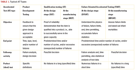
QT is certainly a must. Its objective is to prove that the reliability of the product is above a specified level. In Class I products, this level is usually measured by the percentage of failures per lot and/or by the number of failures per unit time (failure rate). The typical requirement is no more than a few percent failed parts out of the total lot (population). Testing is time limited. Industries cannot do without QT. QT enables one to “reduce to a common denominator” different products, as well as similar products, but produced by different manufacturers. QT reflects the state-of-the-art in a particular field of engineering, and the typical requirements for the product performance.
Today’s QT requirements are only good, however, for what they are intended – to confirm that the given device is qualified into a product to serve more or less satisfactorily in a particular capacity. If a product passes the standardized QT, it is not always clear why it was good, and if it fails the tests, it is often equally unclear what could be done to improve its reliability. It is well known that if a product passes QT, it does not mean there will be no failures in the field, nor is it clear how likely or unlikely these failures might be. Since QT is not failure oriented, it is unable to provide the most important ultimate information about the reliability of a product: the probability of its failure in the field after the given time in service and under the anticipated service conditions.
FOAT, on the other hand, is aimed at revealing and understanding the physics of the expected or occurred failures. Unlike QTs, FOAT is able to detect the possible
failure modes and mechanisms. Another possible objective of the FOAT is, time permitting, to accumulate failure statistics. Thus, FOAT deals with the two major aspects of the RE: physics and statistics of failure. While it is the QT that makes a device into a product, it is the FOAT that enables one to understand the reliability physics behind the product and, based on the appropriate PM, to create a reliable product with the predicted probability of failure. Adequately planned, carefully conducted, and properly interpreted FOAT provides a consistent basis for the prediction of the probability of failure after the given time in service. Well-designed and thoroughly implemented FOAT can facilitate dramatically the solutions to many engineering and business-related problems, associated with the cost-effectiveness and time-to-market. This information can be helpful in understanding what should be possibly changed in the design to create a viable and a reliable product. Almost any structural, materials or technological improvement can be “translated,” using FOAT data, into the probability of failure. That is why FOAT should be conducted in addition to, and, preferably, before the QT, even before the DQTs. There might be also situations when FOAT can be used as an effective substitution for any QT, especially for new products, when acceptable QT standards do not yet exist.
“Shifts” in the modes and/or mechanisms of failure might occur during FOAT, because there is always a temptation to broaden (enhance) the stress as far as possible to achieve the maximum “destructive effect” (FOAT effect) in the shortest period of time. AT conditions may hasten failure mechanisms (“shifts”) that are different from those that could be actually observed in service conditions. Examples are: change in materials properties at high or low temperatures, time-dependent strain due to diffusion, creep at elevated temperatures, occurrence and movement of dislocations caused by an elevated stress, or a situation when a bimodal distribution of failures (a dual mechanism of failure) occurs. Because of the possible shifts, it is always necessary to correctly identify the expected failure modes and mechanisms, and to establish the appropriate stress limits to prevent shifts. It is noteworthy that different failure mechanisms are characterized by different physical phenomena and different activation energies, and therefore, a simple superposition of the effects of two or more failure mechanisms is unacceptable: It can result in erroneous reliability projections.
Burn-in (“screening”) testing (BIT) is aimed at the detection and elimination of infant mortality failures. BIT could be viewed as a special type of manufacturing FOAT (MFOAT). It is needed to stabilize the performance of the device in use. The rationale behind the BIT is based on a concept that mass production of electronic devices generates two categories of products that passed the formal QT: 1) robust (“strong”) components that are not expected to fail in the field, and 2) relatively unreliable (“weak”) components (“freaks”) that, if shipped to the customer, will most likely fail in the field.
BIT is supposed to stimulate failures in defective devices by accelerating the stresses that will most definitely cause these devices to fail. BIT is not supposed to appreciably damage good, “healthy” items. The bathtub curve of a device that underwent BIT is expected to consist of the steady state and wear-out portions only. BIT can be based on high temperatures, thermal cycling, voltage, current density, high humidity, etc. BIT is performed by the manufacturer or by an independent test house. Clearly, for products that will be shipped out to the customer, BIT is a nondestructive test.
BIT is expensive, and therefore, its application must be thoroughly designed and monitored. BIT is mandatory on most high-reliability procurement contracts, such as defense, space, and telecommunication systems; i.e., Class II and III products. Today, BIT is often used for Class I products as well. For military applications, BIT can last as long as a week (168 hr.). For commercial applications, BITs typically do not last longer than two days (48 hr.).
Optimum BIT conditions can be established by assessing the main expected failure modes and their activation energies, and from analysis of the failure statistics during previous BIT. Special investigations are usually required to ensure cost-effective BIT of smaller quantities is acceptable.
A cost-effective simplification can be achieved if BIT is applied to the complete equipment (assembly or subassembly) rather than to an individual component, unless it is a large system fabricated of several separately testable assemblies. Although there is a possibility some defects might escape the BIT, it is more likely that BIT will introduce some damage to the “healthy” product or might “consume” a certain portion of its useful service life: BIT might not only “fight” the infant mortality, but also accelerate the very degradation process that takes place in the actual operation conditions. Some BIT (e.g., high electric fields for dielectric breakdown screening, mechanical stresses below the fatigue limit) is harmless to the materials and structures under test, and does not lead to an appreciable “field life loss.” Others, although not triggering new failure mechanisms, might consume some small portions of the device lifetime. In lasers, the “steady-state” portion of the bathtub diagram is, in effect, not a horizontal, but a slowly rising curve, and wear-out failures occupy a significant portion of the diagram.
FOAT cannot do without simple and meaningful predictive models.5,6 It is on the basis of such models that one decides which parameter should be accelerated, how to process the experimental data and, most important, how to bridge the gap between what one “sees” as a result of the AT and what they will possibly “get” in the actual operation conditions. By considering the fundamental physics that might constrain the final design, PM can result in significant savings of time and expense and shed light on the physics of failure. PM can be very helpful also to predict reliability at conditions other than the FOAT. Modeling can be helpful in optimizing the performance and lifetime of the device, as well as coming up with the best compromise between reliability, cost-effectiveness and time-to-market.
A good FOAT PM does not need to reflect all the possible situations, but should be simple, should clearly indicate what affects what in the given phenomenon or structure, and should be suitable for new applications, new environmental conditions and technology developments, as well as for the accumulation, on its basis, of reliability statistics.
FOAT PMs take inputs from various theoretical analyses, test data, field data, customer and QT spec requirements, state-of-the-art in the given field, consequences of failure for the given failure mode, etc. Before one decides on a particular FOAT PM, they should anticipate the predominant failure mechanism, and then apply the appropriate model. The most widespread PMs identify the MTTF in steady-state-conditions. If one assumes a certain probability density function for the particular failure mechanism, then, for a two-parametric distribution (like the normal or Weibull one), they could construct this function based on the determined MTTF and the measured standard deviation (STD). For single-parametric probability density distribution functions (like an exponential or Rayleigh’s ones), the knowledge of the MTTF is sufficient to determine the failure rate and the probability of failure for the given time in operation.
The most widespread FOAT PMs are power law (used when the physics of failure is unclear); Boltzmann-Arrhenius equation (used when there is a belief that the elevated temperature is the major cause of failure); Coffin-Manson equation (inverse power law; used particularly when there is a need to evaluate the low cycle fatigue lifetime); crack growth equations (used to assess the fracture toughness of brittle materials); Bueche-Zhurkov and Eyring equations (used to assess the MTTF when both the high temperature and stress are viewed as the major causes of failure); Peck equation (used to consider the role of the combined action of the elevated temperature and relative humidity); Black equation (used to consider the roles of the elevated temperature and current density); Miner-Palmgren rule (used to consider the role of fatigue when the yield stress is not exceeded); creep rate equations; weakest link model (used to evaluate the MTTF in extremely brittle materials with defects), and stress-strength interference model, which is, perhaps, the most flexible and well substantiated model.
The Boltzmann-Arrhenius equation (model) 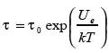 is most widespread in semiconductor reliability and underlies many FOAT related concepts. In this equation, τ is the MTTF, is the activation energy, k=8.6174 x 10⁻⁵eV/ºK is the Boltzmann’s constant, and is the absolute temperature. The equation addresses degradation and aging related processes. The failure rate is found as
 ![]() so that the probability of failure at the moment t of time, if the exponential formula of reliability is used, is
so that the probability of failure at the moment t of time, if the exponential formula of reliability is used, is  . If the probability of failure P is established for the given time t in operation, then this formula can be employed to determine the acceptable failure rate.
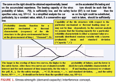
Stress-strength (demand-capacity) interference model (Figure 1) is the most comprehensive and flexible predictive model in reliability engineering.1 It enables one to consider the probabilistic nature of both the stress (demand, load) and strength (capacity) of the system of interest. If necessary and applicable, this model enables one to account for the time dependency of the demand and capacity probability distribution functions. The model might include Boltzmann-Arrhenius, Coffin-Manson and other FOAT models when addressing particular modes of failure.
Typical FOAT Procedure
Probabilistic DfR (PDfR) approach is based on the probabilistic risk management (PRM) concept, and if applied broadly and consistently, brings in the probability measure (dimension) to each of the design characteristics of interest.7-9 Using AT data and, in particular FOAT data, and PM techniques, the PDfR approach enables one to establish, usually with sufficient accuracy, the probability of the possible (anticipated) failure of the device for the given loading conditions and for the given moment of time, both in the field and during FOAT. After the probabilistic PMs are developed and the corresponding predictive algorithms are obtained, one should use sensitivity analyses (SA) to determine the most feasible materials and geometric characteristics of the design, so that the adequate probability of failure is achieved. In other cases, the PDfR approach enables one to find the most feasible compromise between the reliability and cost-effectiveness of the product.
When PDfR is used, the reliability criteria (specifications) are based on the acceptable (allowable) probabilities of failure. Not all products require application of PDfR – only those for which there is reason to believe the probability of failure in the field might not be adequate for particular applications. No one and nothing is perfect. Failures happen and the probability is never zero. The difference between a reliable and unreliable system (device) is in the level of the probability of failure. This probability can be established through specially designed, carefully conducted and thoroughly interpreted DFOAT aimed at understanding the physics of failure.
Usually product reliability is predicated on the reliability of its one or two most vulnerable (most unreliable) functional or structural elements. It is for these elements that the adequate DFOAT should be designed and conducted. SA are a must after the physics of the anticipated failure is established, the appropriate PMs are agreed on, and the acceptable probability of failure in the field is, at least tentatively, specified. SA should be carried out prior to the final decision to mass produce the product. DFOAT is not necessarily a destructive test, but is always a test to failure; i.e., a test to determine limits of the reliable operation and the probability that these limits are exceeded. A priori “probability-of-failure” confirmed by some statistical data (to determine the mean and STD values of the probability distribution of interest, but not necessarily the probability-distribution function itself) can successfully replace time and labor consuming a-posteriori “statistics-of-failure” effort(s).
Technical diagnostics, prognostication and health monitoring (PHM)11 could be effective means to anticipate, establish and prevent possible field failures. It should be emphasized, however, that PHM effort, important as it might be as part of the general reliability approach, is applied at the operation phase of the product and cannot replace the preceding FOAT, DfR, AM or BIT activities. The PDfR approach has to do primarily with the DfR phase of the product’s life, and not with Manufacturing-for-Reliability (MfR) efforts. BIT could be viewed, as has been indicated above, as a special and an important type of MFOAT intended to meet MfR objectives. BIT is mandatory, whatever DfR approach is considered and implemented.
Safety factor (SF) is an important notion of the PDfR approach. While the safety margin (SM), defined as the (random) difference Ψ = C – D between the (random) capacity (strength) and the (random) demand (stress) is a random variable itself, the SF is defined as the ratio 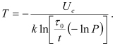 of the mean value
 ![]() of the SM to its STD
of the SM to its STD ![]() , and therefore is a nonrandom PDfR criterion of the reliability (dependability) of an item. It establishes, through the mean value of the SM, the upper limit of the reliability characteristic of interest (such as, stress-at-failure, time-to-failure, the highest possible temperature, etc.) and, through the STD of the SM, the accuracy, with which this characteristic is defined. For instance, for reliability characteristics that follow the normal law, the SF changes from 3.09 to 4.75, when the probability of non-failure (dependability) changes from 0.999000 to 0.999999. As one can see from these data, the direct use of the probability of non-failure might be inconvenient, since, for highly reliable items, this probability is expressed by a number that is very close to unity. For this reason, even significant changes in the item’s (system’s) design, which are expected to have an appreciable impact on its reliability, may have a minor effect on the probability of non-failure. This is especially true for highly reliable (highly dependable) items. If the characteristic (random variable) of interest is time to failure (TTF), the corresponding SF is determined as the ratio of the MTTF to the STD of the TTF.
, and therefore is a nonrandom PDfR criterion of the reliability (dependability) of an item. It establishes, through the mean value of the SM, the upper limit of the reliability characteristic of interest (such as, stress-at-failure, time-to-failure, the highest possible temperature, etc.) and, through the STD of the SM, the accuracy, with which this characteristic is defined. For instance, for reliability characteristics that follow the normal law, the SF changes from 3.09 to 4.75, when the probability of non-failure (dependability) changes from 0.999000 to 0.999999. As one can see from these data, the direct use of the probability of non-failure might be inconvenient, since, for highly reliable items, this probability is expressed by a number that is very close to unity. For this reason, even significant changes in the item’s (system’s) design, which are expected to have an appreciable impact on its reliability, may have a minor effect on the probability of non-failure. This is especially true for highly reliable (highly dependable) items. If the characteristic (random variable) of interest is time to failure (TTF), the corresponding SF is determined as the ratio of the MTTF to the STD of the TTF.
SF is reciprocal to the coefficient of variability (COV). While the COV is a measure of the uncertainty of the random variable of interest, the SF is the measure of certainty, with which the random parameter (stress-at-failure, the highest possible temperature, the ultimate displacement, etc.) is determined.
It is noteworthy that the most widespread FOAT models are aimed at the prediction of the MTTF only and directly. This means a single parametric probability distribution law, such as exponential distribution, is supposed to be used. The SF in this case is always SF=1.
As a simple example of the application of the PDfR concept, let us address a device whose MTTF during steady-state operation is described by the Boltzmann-Arrhenius equation, and assume that the exponential law of reliability is applicable. Solving this equation for the absolute temperature, we obtain:
The given (anticipated) type of failure is surface charge accumulation, for which ![]()
the τ0 value obtained on the basis of the FOAT is τ0 = 2x10⁻⁵ hr., and the allowable (specified) probability of failure at the end of the device’s service time is, say, t = 40,000 hr. is Q = 10-5 i.e., it is acceptable that one out of 100,000 devices fails. With these input data, the above formula indicates that the steady-state operation temperature should not exceed T = 352.3˚K = 79.3˚C for the required reliable operation of the device, so that the thermal management equipment should be designed and its reliable operation should be assured accordingly. This elementary example gives a flavor of what one could possible expect from using a PDfR approach. Other, more in-depth, examples can be found in Refs. 8 and 9. The most general probabilistic approach, based on the use of probability density distribution functions and the cumulative distributions of the random characteristics of interest, is described by Suhir.10
It should be widely recognized and commonly accepted that the probability of a failure is never zero. It could be unacceptably low or unnecessarily high, but never zero. It should be further recognized that this probability could be predicted and, if necessary, specified, controlled and maintained at an acceptable level, and that the effort to establish such a probability does not have to be costly or time-consuming. One effective way to evaluate the probability of failure in the field is to implement the existing methods and approaches of PRM techniques and to develop adequate PDfR methodologies. These methodologies should be based mostly on FOAT and on a widely employed PM effort. FOAT should be carried out in a relatively narrow but highly focused and time-effective fashion for the most vulnerable elements of the design of interest. If the QT has a solid basis in FOAT, PM and PDfR, then there is reason to believe the product of interest will be sufficiently and adequately robust in the field. For superfluously robust, and perhaps, because of that, too costly products, application of FOAT can establish the unnecessary low probability of failure in the field.
The novel QT could be viewed as a “quasi-FOAT,” “mini-FOAT,” a sort-of the “initial stage of the actual FOAT.” Such a “mini-FOAT” more or less adequately replicates the initial non-destructive, yet full-scale, stage of the full-scale FOAT. The duration and conditions of such “mini-FOAT” QT should be established based on the observed and recorded results of the actual FOAT, and should be limited to the stage when no failures, or limited and “prescribed” (anticipated) failures, are observed, and that “what one sees” is in accordance with “what one got (observed)” in the actual full-scale FOAT. PHM technologies could be of a significant help in this effort. “Canaries,” for instance, could be concurrently tested to make sure the safe limit is not exceeded.
We believe that such an approach to qualify devices into products will enable industry to specify, and the manufacturers to ensure, a predicted and adequate probability of failure for a device that passed the QT, and will be operated in the field under the given conditions for the given time. FOAT should be thoroughly implemented, so that the QT is based on the FOAT information and data. PDfR concept should be widely employed. Since FOAT cannot do without predictive modeling, the role of such modeling, both computer-aided and analytical (“mathematical”), in making the suggested new approach to product qualification practical and successful. It is imperative that the reliability physics that underlies the mechanisms and modes of failure is well understood. No progress in coming up with an adequate level of the reliability of a product in the field can be expected if the physics of failure is not understood well. Such an understanding can be achieved only provided that FOAT, PM and PDfR efforts are implemented.
Minimizing Field Failure Risk Steps
- Develop an in-depth understanding of the physics of possible failures. In this respect, there needs to be a continuous effort to ensure and improve the predictability of models; i.e., models must accurately replicate the physics of the problem comprehensively and should be well supported by good materials characterization.
- Validate models through use of relevant experimental techniques such as in-situ sensors, photo-mechanics, etc.
- Neither failure statistics, nor the most effective ways to accommodate failures (such as redundancy, troubleshooting, diagnostics, prognostication, health monitoring, maintenance), can replace an understanding of the physics of failure and good (robust) physical design.
- Assess likelihood (probability) that the anticipated modes and mechanisms might occur in service conditions and minimize likelihood of a failure by selecting the best materials and best physical design.
- Understand and distinguish between different aspects of reliability: operational (functional) performance, structural/mechanical reliability (caused by mechanical loading) and environmental durability (caused by harsh environmental conditions).
- Distinguish between materials and structural reliability and assess the effect of mechanical and environmental behavior of the materials and structures in the design on product functional performance.
- Understand the difference between requirements of qualification specifications and standards, and actual operation conditions. In other words, understand the QT conditions and design the product not only so it would withstand operation conditions on a short- and long-term basis, but also to pass QT.
- Understand role and importance of FOAT, the PDfR and conduct PM whenever and wherever possible.
Ephraim Suhir, Ph.D., is Distinguished Member of Technical Staff (retired), Bell Laboratories’ Physical Sciences and Engineering Research Division, and is a professor with the University of California, Santa Cruz, University of Maryland, and ERS Co.; suhire@aol.com.
Ravi Mahajan, Ph.D., is senior principal engineer in Assembly Pathfinding, Assembly and Test Technology Development, Intel (www.intel.com); ravi.v.mahajan@intel.com.
References
1. E. Suhir, “Applied Probability for Engineers and Scientists,” McGraw Hill, New York, 1997.
2. E. Suhir, “How to Make a Device into a Product: Accelerated Life Testing, Its Role, Attributes, Challenges, Pitfalls, and Interaction with Qualification Testing,” E. Suhir, CP Wong, YC Lee, eds. “Micro- and Opto-Electronic Materials and Structures: Physics, Mechanics, Design, Packaging, Reliability,” Springer, 2007.
3. E.Suhir, “Reliability and Accelerated Life Testing,” Semiconductor International, February 1, 2005.
4. A. Katz, M. Pecht and E. Suhir, “Accelerated Testing in Microelectronics: Review, Pitfalls and New Developments,” Proceedings of the International Symposium on Microelectronics and Packaging, IMAPS, Israel, 2000.
5. E. Suhir, “Thermo-Mechanical Stress Modeling in Microelectronics and Photonics,” Electronic Cooling, vol. 7, no. 4, 2001.
6. E. Suhir, “Thermal Stress Modeling in Microelectronics and Photonics Packaging, and the Application of the Probabilistic Approach: Review and Extension,” IMAPS International Journal of Microcircuits and Electronic Packaging, vol. 23, no. 2, 2000.
7. E. Suhir and B. Poborets, “Solder Glass Attachment in Cerdip/Cerquad Packages: Thermally Induced Stresses and Mechanical Reliability,” Proceedings of the 40th ECTC, May 1990; see also: ASME Journal of Electronic Packaging, vol. 112, no. 2, 1990.
8. E. Suhir, “Probabilistic Approach to Evaluate Improvements in the Reliability of Chip-Substrate (Chip-Card) Assembly,” IEEE CPMT Transactions, Part A, vol. 20, no. 1, 1997.
9. E. Suhir, “Probabilistic Design for Reliability (PDfR),” ChipScale Review, vol. 14, no. 6, 2010.
10. E. Suhir and R. Mahajan, “Probabilistic Design for Reliability (PDfR) and a Novel Approach to Qualification Testing,” IEEE CPMT Transactions, submitted for publication.
11. M.G. Pecht, Prognostics and Health Management in Electronics, John Wiley, 2009.


Press Releases
- Seika Machinery’s SMI 2026 Webinar Series Continues with Focus on PCB Cleaning Before Solder Paste Printing
- Forwessun Expands Testing Capabilities through Strategic TRI Alliance
- Federal Electronics Expands Advanced Manufacturing Capabilities to Support Military and Aerospace Cable Assembly and Wire Harness Programs
- Altus Continues Irish Growth with Expansion of Engineering Team