

2005 Articles
Let it Flow
A short reflow profile causes flux entrapment under low standoff components.
During reflow soldering it is important to allow time for good solder flow, as well as time for flux to complex and move from a tacky state to a hard and insulative state. If ample time is not permitted for flux to volatilize, harmful (conductive and moisture-absorbing) residues inherent in flux chemistries will remain and create potential for electrochemical failures. Often, it is not temperature that needs to be modified in reflow profiles, but rather the time above liquidus that needs to be increased.
One customer was experiencing product failures around a low standoff component area under high humidity conditions. There was an invisible leakage pathway in and around this specific component. The product was built with a no-clean, double-reflow, single-pallet process.
|
|
The first investigative step involved a site visit to where the failing assemblies were being built. These site visits often reveal processing anomalies. In this case, however, the assembly process used very good techniques and well-trained operators. There was good solder deposition during reflow and good hand soldering techniques with no additional flux or evidence of solderballs and splatters. The only noticeable potential flaw: the reflow profile was somewhat quick, and it was questionable whether solder was held above liquidus for a long enough time to fully volatilize and complex the no-clean flux.
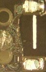
To investigate this failure mechanism thoroughly, Foresite conducted visual analysis and ion chromatography (IC) with C3 localized extraction techniques and SIR testing. Visually, all bare HASL boards showed no noticeable residues. However, the failing area on the assemblies showed visible flux residues between the power lead and cap as well as an excess of heavy, gooey flux, especially between the board and component body below the low standoff component (Figure 1). Looking at a good working unit, no visible flux residues or excess flux was visible.
Following this visual inspection, we performed IC testing utilizing C3 localized extraction techniques to examine the failing areas individually. Our findings revealed marginally high levels of chloride and high levels of weak organic acid flux residues underneath and around the low standoff components. These residue levels on an SMT process pose a risk for corrosion and current leakage. We also tested incoming components from the failure area, and found that they were high in chloride, which was the contributor to the chloride levels in the final assemblies. This level of chloride was attributable to poor quality rinse water in the manufacturing of the components.
We followed the IC testing with SIR testing to correlate the residue levels with actual electrical performance. The assemblies with no visible flux residues showed good high resistance levels in high humidity. SIR testing of the gooey flux areas showed poor electrical performance results in high humidity, creating leakage pathways. This showed that the areas of heavy flux that were not fully complexed posed a great risk of leakage and corrosion problems due to the levels of ionic residues present. This verified our thoughts from the on-site visit. Some of this residue was trapped underneath the component bodies as it tried to volatilize, leaving behind the gooey flux that was suspect in these failures. We urged this customer to add 10 to 15 seconds to its reflow profile to permit flux to fully complex.
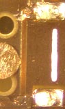
The customer tried the modified reflow profile we suggested, and sent more samples for visual, IC and SIR analysis. Visually, the flux residues were now hardened and insulative (Figure 2). Areas around and below the formerly failing component area now showed good localized IC results with ion levels well below our recommended limits for long-term reliable electrical performance. SIR testing confirmed these results by showing good resistance levels in the areas that were formerly failing. By switching the reflow profile to permit enough time for flux to fully volatilize, potentially harmful residues were able to complex, leaving only a hard and insulative residue not prone to moisture absorption and electrical leakage pathways.
Terry Munson is with Foresite Inc. (residues.com); tm_foresite@residues.com. His column appears monthly.


Press Releases
- Altus Group Invests in Major Headquarters Expansion to Showcase Complete Turnkey Manufacturing Capability
- ViTrox Americas Welcomes Eric Cruz as Technical Support Engineer
- ECD Strengthens Engineering Team with New Software Development Hire
- ViTrox Americas Welcomes Doug Ennis as Senior Field Applications & Service Engineer