

2005 Articles
Program for Calculation of Flip-Chip Standoff Height
Direct calculation is important, but tedious and time-consuming. Until now, that is.
Last March, the approximately 60 scientists from the research divisions at MCNC Research & Development Institute were acquired by RTI Microelectronic. Interconnection and packaging have always been a core competency of these researchers. The results have been manifested in a number of patents and the spinout of Unitive (now a division of Amkor) for high-volume wafer bumping. RTI now studies high-density interconnection using through-silicon vias to interconnect 3-D stacked silicon ICs. The following example of a unique RTI packaging application was conducted in collaboration with neighboring universities. Wafer-level solder bumping was used to prepare ICs for flip-chip attach (FCA) to a multi-chip module (MCM). While these requirements alone did not pose any significant challenges, the fact that these were submerged solder bumps posed a unique series of opportunities. The collaborating research teams at North Carolina State and RTI aimed to control the gap between the IC and the MCM within ±1 µm to facilitate reproducible capacitive and inductive coupling.
To ensure a repeatable standoff gap within ±1 µm, a few key parameters had to be closely controlled and calculated. A user-friendly computer program was generated to facilitate the easy input of parameters (e.g., bump pad diameter, plated solder height and column diameter) and to perform the solder bump volume and bump height calculations that translated into accurate predictions of flip-chip standoff heights.
Direct calculation of solder bump standoff height in a flip-chip package is very important but tedious and time-consuming. The tediousness is caused by the complexity of the equations involving the parameters of the solder bump and joint geometries. The novel Flip Chip Stand-off Height Calculator can be used to compute the required height of the starting cone shaped solder bump or ending double-truncated spherical shaped joint, and vice-versa.
The solder bumping process requires that solder be deposited on an under-bump metalization on a chip bond pad. The bumped die is placed on the substrate pads and the assembly is heated to make a double-truncated spherical shaped solder connection. This calculator works under the theory of conservation of mass and the assumptions that (i) molten solder droplet deforms into a truncated sphere and a double truncated sphere, respectively, when it comes into contact with a planar substrate and sandwich between two planer substrates and (ii) the densities of the starting solder bump and the ending solder joint remain the same (i.e., the volume remains unchanged).
From Figure 1, the volume of truncated cone and double-truncated sphere are, respectively,
![]()
 FIGURE 1: Schematic with relevant cross-sectional dimensions of solder structures.
 |
When the angle, Th, of the truncated cone is known, D2 can obtained from
![]()
The volume of a single truncated sphere can be obtained by putting W2 = 0, resulting in
Based on stated theory and assumptions, the volumes of the starting geometry and the ending geometry are equated. The desired height is calculated using Newton’s root extraction method. Figures 2 and 3 are screen shots of the calculator program interface. The program easily calculates bump heights (before FCA) and predicts flip-chip standoff gaps after attachment. The program, a Visual Basic file, is available from the authors upon request.
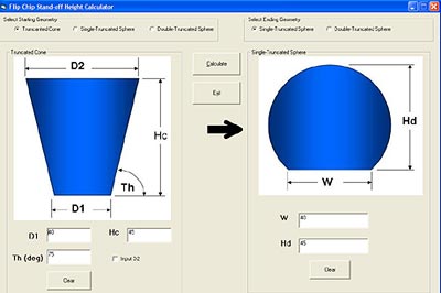 FIGURE 2: Screen shot of bump height using novel calculator.
 |
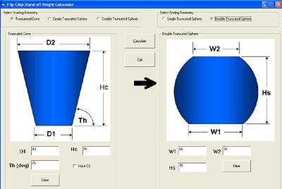 FIGURE 3: Screen shot of FCA standoff gap using novel calculator.
 |
Acknowledgments
Support for the Solder Volume Calculator Program was provided by the U.S. Air Force under the AC Coupled Interconnect Program. The authors wish to thank Dr. Paul Franzon and Dr. John Wilson of North Carolina State and our fellow researchers at RTI for their contributions.
Joshua Ampofo is a Ph.D. student in mechanical engineering at North Carolina A&T State University (ncat.edu); auspi@hotmail.com; Richard LaBennett is manager, optical and electronic packaging group, at RTI International (rti.org); rlabennett@rti.org; Stephen Akwaboa is a Ph.D. candidate at NC A&T; Dr. Frederick Ferguson is professor and NASA CAR director, NC A&T.


Press Releases
- Altus Group Invests in Major Headquarters Expansion to Showcase Complete Turnkey Manufacturing Capability
- ViTrox Americas Welcomes Eric Cruz as Technical Support Engineer
- ECD Strengthens Engineering Team with New Software Development Hire
- ViTrox Americas Welcomes Doug Ennis as Senior Field Applications & Service Engineer