

Current Issue
Capacitor Testing Challenges and Solutions
Chip caps are prone to leakage, so consider these test methods for minimizing electrical failures.
Capacitors are widely used for bypassing, coupling, filtering and tunneling electronic circuits. However, to be useful, their capacitance value, voltage rating, temperature coefficient and leakage resistance must be characterized. Although capacitor manufacturers perform these tests, many electronics assemblers also perform some of these tests as quality checks. This article looks at some of the challenges associated with capacitor testing, as well as some of the test techniques used.
A capacitor is somewhat like a battery in that they both store electrical energy. Inside a battery, chemical reactions produce electrons on one terminal and store electrons on the other. However, a capacitor is much simpler than a battery because it can’t produce new electrons – it only stores them. Inside the capacitor, the terminals connect to two metal plates separated by a non-conducting substance known as a dielectric.
A capacitor’s storage potential, or capacitance, is measured in farads. A one-farad (1 F) capacitor can store one coulomb (1 C) of charge at one volt (1 V). A coulomb is 6.25´1018 electronics. One amp represents a rate of electron flow of 1C of electrons per second, so a 1 F capacitor can hold one amp-second (1 A/s) of electrons at 1 V.
The coulomb’s function of an electrometer can be used with a step voltage source to measure capacitance levels ranging from <10pF to hundreds of nanofarads.
The unknown capacitance is connected in series with the electrometer input and the step voltage source.
The calculation of the capacitance is based on this equation:
Figure 1 illustrates a basic configuration for measuring capacitance with an electrometer with an internal voltage source. The instrument is used in the charge (or coulombs) mode, and its voltage source provides the step voltage. Just before the voltage source is turned on, the meter’s zero check function should be disabled and the charge reading suppressed by using the REL function to zero the display. (The purpose of zero check is to protect the input FET from overload and to zero the instrument. When zero check is enabled, the input of the electrometer is a resistance from roughly 10 MΩ to 100 MΩ, depending on the electrometer used. Zero check should be enabled when changing conditions on the input circuit, such as changing functions and connections. The REL function subtracts a reference value from actual readings. When REL is enabled, the instrument uses the present reading as a relative value. Subsequent readings will be the difference between the actual input value and the relative value.)
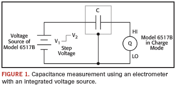
Then, the voltage source should be turned on and the charge reading noted immediately. The capacitance can then be calculated from:
where
Q2 = final charge
Q1 = initial charge (assumed to be zero)
V2 = step voltage
V1 = initial voltage (assumed to be zero)
After the reading has been recorded, reset the voltage source to 0 V to dissipate the charge from the device. Before handling the device, verify the capacitance has been discharged to a safe level. The unknown capacitance should be in a shielded test fixture. The shield is connected to the LO input terminal of the electrometer. The HI input terminal should be connected to the highest impedance terminal of the unknown capacitance. If the rate of charge is too great, the resulting measurement will be in error because the input stage becomes temporarily saturated. To limit the rate of charge transfer at the input of the electrometer, add a resistor in series between the voltage source and the capacitance. This is especially true for capacitance values >1 nF. A typical series resistor would be 10 kΩ to 1 MΩ.
Capacitor Leakage
Leakage is one of the less-than-ideal properties of a capacitor, expressed in terms of its insulation resistance (IR). For a given dielectric material, the effective parallel resistance is inversely proportional to the capacitance. This is because the resistance is proportional to the thickness of the dielectric, and inverse to the capacitive area. The capacitance is proportional to the area and inverse to the separation. Therefore, a common unit for quantifying capacitor leakage is the product of its capacitance and its leakage resistance, usually expressed in megohms-microfarads (MΩ·µF). Capacitor leakage is measured by applying a fixed voltage to the capacitor under test and measuring the resulting current. The leakage current will decay exponentially with time, so it’s usually necessary to apply the voltage for a known period (the soak time) before measuring the current.
In theory, a capacitor’s dielectric could be made of any non-conductive substance. However, for practical applications, specific materials are used that best suit the capacitor’s function. The insulation resistance of polymer dielectrics, such as polystyrene, polycarbonate or Teflon, can range from 104 MΩ·µF to 108 MΩ·µF, depending on the specific materials used and their purity. For example, a 1000 pF Teflon cap with an insulation resistance higher than 1017 Ω is specified as >108 MΩ·µF. The insulation resistance of ceramics such as X7R or NPO can be anywhere from 103 MΩ·µF to 106 MΩ·µF. Electrolytic capacitors such as tantalum or aluminum have much lower leakage resistances, typically ranging from 1MΩ·μF to 100 MΩ·µF. For example, a 4.7 µF aluminum cap specified as 50 MΩ·µF is guaranteed to have at least 10.6 MΩ insulation resistance.
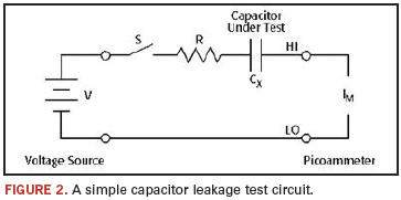
Capacitor leakage test method. Figure 2 illustrates a general circuit for testing capacitor leakage. Here, the voltage is placed across the capacitor (CX) for the soak period; then the ammeter measures the current after this period has elapsed. The resistor (R), which is in series with the capacitor, serves two important functions. First, it limits the current, in case the capacitor becomes shorted. Second, the decreasing reactance of the capacitor with increasing frequency will increase the gain of the feedback ammeter. The resistor limits this increase in gain to a finite value. A reasonable value is one that results in an RC product from 0.5 to 2 sec. The switch (S), while not strictly necessary, is included in the circuit to allow control over the voltage to be applied to the capacitor.
The series resistor also adds Johnson noise – the thermal noise created by any resistor – to the measurement. At room temperature, this is roughly 6.5×10¹⁰ amps, p-p. The current noise in a 1 TΩ feedback resistor at a typical 3 Hz bandwidth would be ~8×10-16 A. When measuring an insulation resistance of 1016Ω at 10 V, the noise current will be 80% of the measured current.
Alternate test circuit. Greater measurement accuracy can be achieved by including a forward-biased diode (D) in the circuit (Figure 3). The diode acts like a variable resistance, low when the charging current to the capacitor is high, then increases in value as the current decreases with time. This allows the series resistor used to be much smaller because it is only needed to prevent overload of the voltage source and damage to the diode if the capacitor is short-circuited. The diode used should be a small signal diode, such as a 1N914 or a 1N3595, but it must be housed in a light-tight enclosure to eliminate photoelectric and electrostatic interference. For dual-polarity tests, two diodes should be used back to back in parallel.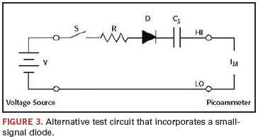
Test Hardware Considerations
A variety of considerations go into the selection of the instrumentation used when measuring capacitor leakage:
- Although it is certainly possible to set up a system with a separate voltage source, an integrated one simplifies the configuration and programming process significantly, so look for an electrometer or picoammeter with a built-in variable voltage source. A continuously variable voltage source calculates voltage coefficients easily. For making high-resistance measurements on capacitors with high voltage ratings, consider a 1000 V source with built-in current limiting. For a given capacitor, a larger applied voltage within the voltage rating of the capacitor will produce a larger leakage current. Measuring a larger current with the same intrinsic noise floor produces a greater signal-to-noise ratio and, therefore, a more accurate reading.
- Temperature and humidity can have a significant effect on high-resistance measurements, so monitoring, regulating and recording these conditions can be critical to ensuring measurement accuracy. Some electrometers monitor temperature and humidity simultaneously. This provides a record of conditions, and permits easier determination of temperature coefficients. Automatic time-stamping of readings provides a further record for time-resolved measurements.
- Incorporating switching hardware into the test setup allows automating the testing process. For small batch testing in a lab with a benchtop test setup, consider an electrometer that offers the convenience of a plug-in switching card. For testing larger batches of capacitors, look for an instrument that can integrate easily with a switching system capable of higher channel counts.
Configuration examples. Producing enough useful data for statistical analysis requires testing a large quantity of capacitors quickly. Obviously, performing these tests manually is impractical, so an automated test system is required. Figure 4 illustrates such a system, which employs an electrometer with built-in voltage source, as well as a switching mainframe that houses a low current scanner card and a Form C switching card. In this test setup, a single instrument provides both the voltage sourcing and low current measurement functions. A computer controls the instruments to perform the tests automatically.
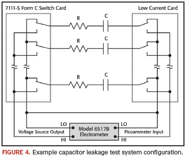
One set of switches is used to apply the test voltage to each capacitor in turn; a second set of switches connects each capacitor to the electrometer’s picoammeter input after a suitable soak period. After the capacitors have been tested, the voltage source should be set to zero, and then some time allowed so the capacitors can discharge before they are removed from the test fixture.
Note that in Figure 4 the capacitors have a discharge path through the normally closed contacts of the relays. To prevent electric shock, test connections must be configured in such a way that the user cannot come in contact with the conductors, connections or DUT. Safe installation requires proper shielding, barriers and grounding to prevent contact with conductors.
More complex test systems that combine leakage measurement with capacitance measurements, dielectric absorption and other tests, if desired, are possible. A simplified schematic of such a test system using an LCZ bridge and a picoammeter with a voltage source is shown in Figure 5.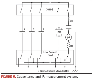
Test System Safety
Many electrical test systems or instruments are capable of measuring or sourcing hazardous voltage and power levels. It is also possible, under single fault conditions (e.g., a programming error or an instrument failure), to output hazardous levels, even when the system indicates no hazard is present. These high-voltage and power levels make it essential to protect operators from any of these hazards at all times. It is the responsibility of the test system designers, integrators and installers to make sure operator and maintenance personnel protection is in place and effective. Protection methods include:
- Design test fixtures to prevent operator contact with any hazardous circuit.
- Make sure the device under test is fully enclosed to protect the operator from any flying debris.
- Double insulate all electrical connections that an operator could touch. Double insulation ensures the operator is still protected, even if one insulation layer fails.
- Use high-reliability, fail-safe interlock switches to disconnect power sources when a test fixture cover is opened.
- Where possible, use automated handlers so operators do not require access to the inside of the test fixture.
- Provide proper training to all users of the system so they understand all potential hazards and know how to protect themselves from injury.
Dale Cigoy is lead applications engineer at Keithley Instruments (keithley.com); dcigoy@keithley.com.


Press Releases
- Amtech Electrocircuits Launches First Article to Deliver Practical AI Insights for Hardtech Manufacturers
- AIM Solder Promotes David Solis to Senior Technical Applications and Laboratory Support Engineer
- SEMI and TechSearch International Release 2026 Edition of Worldwide Assembly & Test Facility Database
- Koh Young America promotes Heriberto Cuevas to Country Manager of its Mexico and South America Operations