

Current Issue
Verifying PCBA Cleanliness with Ion Chromatography
The tool is ideal for localizing contamination and process control.
Cleanliness of printed circuit board assemblies is a critical quality output of any electronics manufacturing facility. If a PCBA is not cleaned sufficiently, the substances remaining may grow dendrites, which can lead to product failure. One effective tool to verify PCBA cleanliness is ion chromatography.
Ion chromatography is a technique to analyze a liquid sample. It tests and determines ionic contamination, identifies which ions are present, and measures overall cleanliness of PCBAs and components. The goals of using IC are to assess product cleanliness, assembly cleaning equipment capability and the overall cleaning process.
Ion chromatography (and its associated equipment) constitutes a different process than that of the ionograph. Both determine whether ionic contamination is present. The major difference is ion chromatography will detect if specific ions are present in the sample and determine the spectrum of the potential contamination. Another benefit is localized verification of cleanliness of a specific component or area of concern, whereas the ionograph can assess only an entire assembly. If a potential cleaning issue is highlighted for a low-profile SMT component, a local extraction of the area can be assessed to determine which ions are present and the potential source of the contamination. An ion chromatography system is typically more expensive than an ionograph and requires an increased cycle time to prepare, measure and analyze the sample.
A standard is used to verify the system is working properly before an actual sample is measured and analyzed. One industry standard used is a seven anion method that includes fluoride, chloride, phosphate, nitrite, bromide, nitrate and sulfate. FIGURE 1 details the spectrum of the standard and the seven elements that constitute the standard.
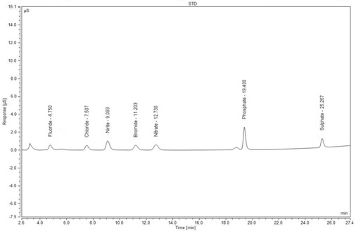
FIGURE 1. Spectrum of seven anion standard.
The results of the equipment analysis include plotting the specific element detected, time interval and intensity of the element peak. Key to any sample is the peak intensity and element detected, which will point to potential contamination issues.
One industry cleanliness test standard used is IPC-TM-650, test method 2.3.28B.1 The method prepares the extracted sample for analysis by dissolving small amounts of residue into the standard (typically IPA and DI water), and then placing the sample in an 80°C ±2°C heated bath for one hour. After heating, the sample is ready to be inserted into the IC equipment for analysis.
PCB Qualification and Process Control
During the qualification process of the printed circuit assembly, ion chromatography can be used to verify the cleanliness of the process and materials used. The scope of the qualification can focus on total assembly cleanliness or be focused on processes such as SMT, wave solder, hand solder operations, or specific low-clearance components (or no clearance) where potential exists for ionic entrapment.
Among the ongoing challenges with PCB manufacturing is low-clearance and no-clearance component packages. These types of components are susceptible to ionic entrapment and potentially assembly reliability issues. Localized analysis can be beneficial to isolate a potential component, process or technology problem. On occasion, test vehicles can be processed and analyzed to isolate potential cleanliness problem areas.
A process control program can be created to continuously verify the assembly cleaning process. The checks can verify cleanliness of DI water wash, batch wash or any other cleaning systems. The following areas can be verified and tracked over time as statistical process control points:
• Incoming components and printed circuit board cleanliness.
• Assembly process, including SMT, wave solder and hand soldering.
• Verification of cleanliness before outside processing, such as conformal coat, underfill, etc.
One note of caution when analyzing cleanliness: Non-wettable components, press-fit connectors or especially hardware that may be assembled to the PCBA may contain oils or other substances from the machining and overall component assembly process. Analysis may give false results. The key is to understand the types of components on the assembly during extraction and know the potential for a false reading may occur.
Cleanliness Failure Analysis
Normalizing ion chromatography results will provide statistical control. Another industry standard focuses on micrograms of sodium chloride per square inch to calculate the ionic density.2 The calculation extracts data from the analysis spectrum per the squared area of the assembly analyzed in inches. The calculation then can be compared to limits dependent on the product, technology and end-use.
The spectrum signature of process manufacturing materials (solders, fluxes, etc.) can be used to determine potential sources of contamination or foreign matter. FIGURE 2 shows a rework organic acid (OA) flux signature. Having signatures on hand to compare as issues arise is helpful to determine if cross-contamination has occurred or does not match any of the manufacturing materials used in the facility. If no matches occur, additional testing and analysis may be required to determine the exact contamination source.
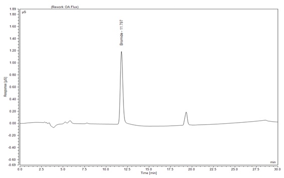
FIGURE 2. Manufacturing flux spectrum signature.
Conclusion
Cleanliness of printed circuit board assemblies (PCBA) is a critical quality output of any electronics manufacturing facility. Ion chromatography is a tool to analyze and verify PCBA cleanliness. One benefit of ion chromatography is localized extraction, which is helpful when determining the root cause of a contamination, in addition to potential long-term cleanliness and reliability concerns of low- or no-clearance components. Finally, ion chromatography can be used as a process control tool to continuously verify the assembly process, ensuring the cleaning systems in place are working to specification.
References
1. IPC-TM-650, Test Methods Manual, method 2.3.28B, “Ionic Analysis of Circuit Boards, Ion Chromatography Method,” November 2012.
2. IPC-TM-650, Test Methods Manual, method 2.3.28D, “Detection and Measurement of Ionizable Surface Contaminants by Resistivity of Solvent Extract (ROSE),” November 2012.
Acknowledgments
I would like to thank and acknowledge Paymon Adl-Zarabi at Benchmark Electronics’ Nashua, NH, division for his insight, assistance and contributions to this article.
is manufacturing staff engineer and environmental management representative, Benchmark Electronics, New Hampshire division (bench.com), and a contributing author to Green Electronics – Design and Manufacturing; scott.mazur@bench.com.


