Taking off the Mask
 How proper investigative work can alleviate misguided print process adjustments.
Printing is arguably one of the most sensitive processes within the entire PCB assembly operation. Not surprisingly, stencil printing’s multi-input interdependency and sensitivity have become more pronounced as miniaturization has taken hold. Even slight variations can cause process shifts, a reality our team was reminded of while conducting recent internal testing.
Our engineers set up a test with a really long board run to evaluate time to bridge, a fairly standard analysis used to understand how many PCBs can be printed for a particular product until solder paste bridging begins to appear. The evaluation, which was performed using a relatively complex ASM test board, was proceeding beautifully until we noticed a sudden shift in the output. The measurable Sigma shift went from a process running at 4 Sigma (1.33 Cpk) to 3 Sigma (1.0 Cpk). The engineer running the evaluation was looking at the process window and robustness, beginning at a 10,000 ft. view with a box plot, which gives reasonable stability insight across the entire run. When a more granular examination of the data was conducted, the data spike appeared on three boards in the batch, with one PCB being more extreme.
To be clear, the data did not show bridging at the point at which the shift was observed, and in fact, the board at 1.0 Cpk was still within the specification range. But, seeing this unusual spike indicated that if the trend continued, the process would most certainly become out of control. The printed boards were put back through solder paste inspection (SPI) to verify repeatability, and, indeed, it was confirmed. The chance of SPI having a wobble exactly on the same board was remote, and we ran it three different times. So, the culprit wasn’t SPI but rather some characteristic with the board or other input.
The solder deposit on the board before the errant PCB and the board after looked fairly similar; these were the three with Sigma shifts. The list of potential candidates for the cause of the problem included the normal things one would consider: mesh fatigue on the stencil, debris on the squeegee, something in the paste roll, etc. All were reviewed, and none was determined problematic. Eventually, our team got down to close inspection of the board and discovered the solder mask on the three outlier PCBs had a different characteristic, a different shape than the other boards. The figures compare standard solder mask and non-standard solder mask. With the good, 4 Sigma boards, the mask came down in one consistent slope to the pad (FIGURE 1). The triad of 3 Sigma boards had solder mask that was slightly thicker than the others and it stepped down to the pad, almost like a stair step (FIGURE 2). On the compromised boards, the solder mask was also closer to the pad, and the combination of the odd shape and the proximity to the pad interfered with the board-to-stencil gasket.
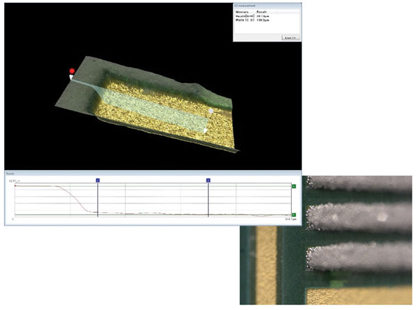
Figure 1. Standard solder mask rolls down to the pad in a consistently sloped plane, permitting robust gasketing.
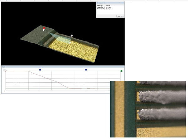
Figure 2. Nonstandard solder mask steps down to the pad, resulting in poor gasketing and an opportunity for process variation.
For assemblers, there are lessons to be learned here. This experience underscores how incredibly sensitive the printing process is. For us – and we source our boards from a respected supplier – with board runs that were evaluation volumes and certainly not ultra high volume, it was fairly easy to isolate, even though all the boards (good and bad) were part of the same batch number. For a manufacturer, however, this could be a red herring, and one might adjust the printer to attempt to correct the issue. However, when a shift in the process is observed, it is highly advisable to look a bit deeper than the print platform. It’s easy to assume it’s the equipment. More times than not when it comes to printing, however, it is an input other than the sophisticated machinery. Take it slow. Don’t immediately start twisting knobs and pushing buttons. Do the investigative work, and good results will follow.
is global applied process engineering manager at ASM Assembly Systems, Printing Solutions Division (asmpt.com); clive.ashmore@asmpt.com. His column appears bimonthly.


