Improper Solderability Testing of QFNs
 For leadless parts, the magic is in the method.
Solder dip or float testing is often used in the industry as it is quick, simple and cheap. But, it can lead to incorrect solderability assessments.
As seen in FIGURE 1, the solderability of the terminations was good, but the test method for this type of a bottom termination component (BTC) is not appropriate.
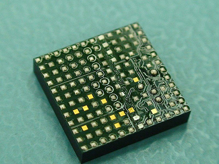
Figure 1. A QFN following solder float test.
The correct and simple way is to use solder paste and a glass plate as a process simulation test, as set forth in IPC standards. The stencil for assembly is used to print paste on a glass slide, the component is placed and reflowed, and the pads examined. Alternatively, wetting balance can be used on the edge pads, as it gives the best opportunity to directly measure wetting force and is easier to align the sample and solder pellet. Longer preheat is required on parts of this type due to the high mass. Component testing using a wetting balance is shown in FIGURE 2.
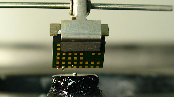
Figure 2. Wetting balance measurement of QFN.
These are typical defects shown in the National Physical Laboratory’s interactive assembly and soldering defects database. The database (http://defectsdatabase.npl.co.uk), available to all this publication’s readers, allows engineers to search and view countless defects and solutions, or to submit defects online. To complement the defect of the month, NPL features the Defect Video of the Month, presented online by Bob Willis. This describes over 20 different failure modes, many with video examples of the defect occurring in real time.
is a consultant at the National Physical Laboratory (npl.co.uk); martin.wickham@npl.co.uk. His column appears monthly.


