Voiding Characteristics of AuSn Solder Paste Flux Vehicles Applied in High-Power LED Module Array Applications
Narrowing the choices of the best flux vehicle.
A high-power LED (light-emitting diode) is defined as an LED package that operates at 1W of power or higher. LEDs are semiconductor-based diodes that emit light when a forward voltage is applied. This permits a small form factor to produce a lot of light while maintaining fantastic efficiency, permitting a single LED to pump out hundreds, or even thousands, of lumens. The high-power LED market thrives on the widening application base of LEDs, specifically in the automotive industry, due to an increasing number of government initiatives that promote energy conservation and efficiency. Other factors that contribute to their use include small size; long life and continuous usage; less power consumption and low voltage; and an increasing number of high-brightness applications.
High-power LEDs provide not only much higher levels of light output than traditional LEDs, but also higher levels of performance, which leads to a longer lifetime of the device. The tradeoff is that a large amount of heat is generated, and in a small, localized area. Since the temperature per unit is so high with high-power LEDs, a high-melting and high-reliable solder is required for assembly. Also critical to the LED assembly process is a void-free solder interface between the diode and its substrate. This provides the thermal and electrical connections needed to generate a stable transmission of light and permits efficient heat transfer to maintain the temperature stability of the device.
80Au20Sn paste is generally chosen as the solder material in high-power LED applications due to its high-melting temperature and reliability in high-volume production. While there is a high upfront cost of investing in luminaires that use high power LEDs as the light source, the optical power, lumen maintenance and reliability of high-power LEDs often translate to a return on investment significantly higher than that from using low- to mid-power LEDs. To meet market demands of a void-free solder interface, voiding in the solder joint should be below 15%.
Two no-clean and six water-soluble flux vehicles were mixed with 80Au20Sn solder powder to analyze the voiding characterizations of each 80Au20Sn solder paste. The results will determine the best 80Au20Sn paste offerings, one no-clean and one water-soluble, for the high-temperature/gold market; specifically for use with high-power LEDs.
Experimental and Results
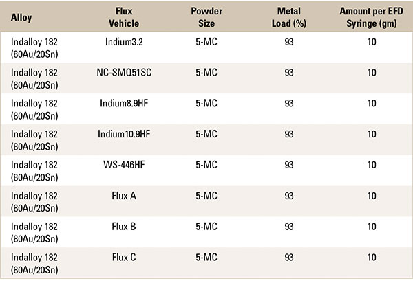
The experiment began by mixing 80Au20Sn Type 5 solder powder with each flux vehicle to create eight 93% metal-load 80Au20Sn solder pastes (TABLE 1).
Table 1. Materials Used
Each 80Au20Sn solder paste was hand-stenciled onto six Cu coupons in a 3x3 square formation (FIGURE 1). A program was created for automated die placement on the Juki pick-and-place machine, which placed nine Cu dies on each Cu coupon (FIGURE 2). The coupons were then reflowed through a BTU furnace with an optimized profile on the back of a DART board – three coupons in air, and three coupons in a nitrogen atmosphere (FIGURE 3).
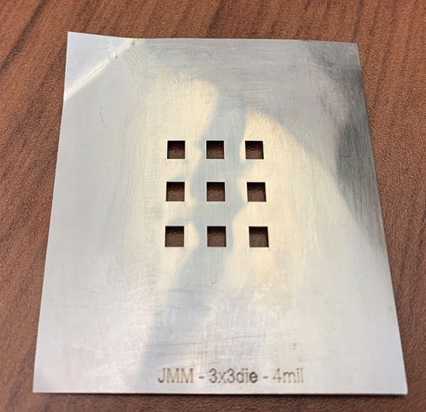
Figure 1. The 3x3 square Cu coupon.
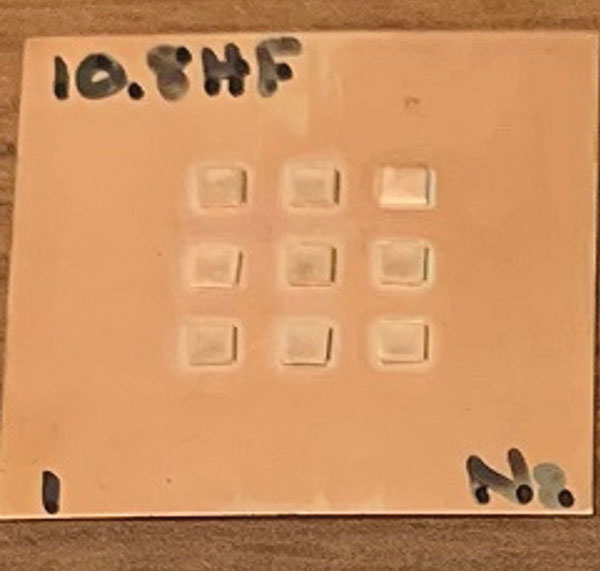
Figure 2. Dies were then placed on each coupon.
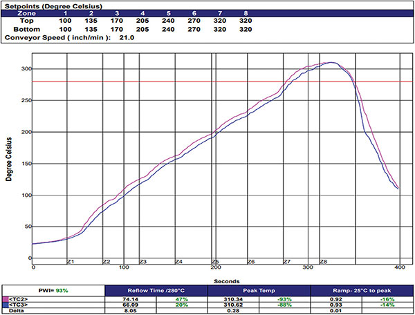
Figure 3. Profile of the reflow oven.
Each coupon was analyzed for data collection using a Yxlon x-ray camera and a voiding calculator. As the die orientation in the tape-and-reel packaging was not specified, dies were placed on the coupons in both “cup up” and “cup down” positions (FIGURE 4). “Cup down” positions have a tendency to trap voids, potentially skewing the data, so only the dies placed in a “cup up” orientation were used for voiding analysis (FIGURE 5).

Figure 4. The “cup up” and “cup down” configurations.
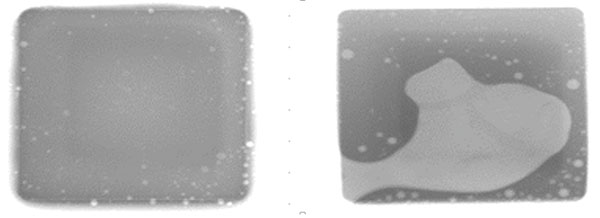
Figure 5. Dies placed in a “cup up” orientation were used for voiding analysis.
Data were interpreted using the one-way ANOVA data analysis and Tukey-Kramer comparisons in air and nitrogen environments (FIGURES 6 and 7).
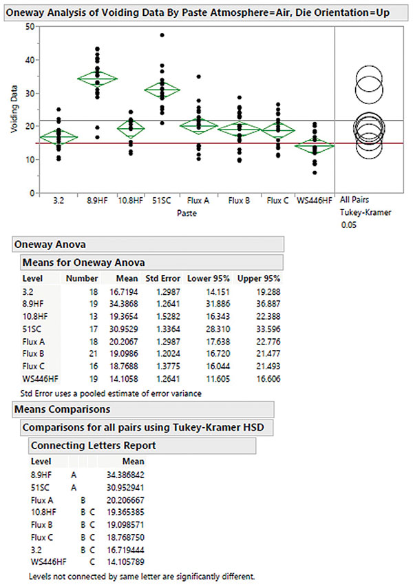
Figure 6. One-way ANOVA and Tukey-Kramer data comparisons in air …
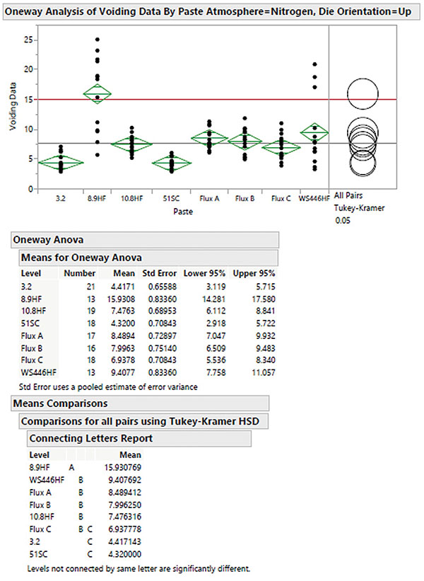
Figure 7. … And in nitrogen.
Reflow performed in a nitrogen atmosphere reduced voiding across all flux vehicles. The flux vehicles with the lowest statistical voiding were WS-446HF and Indium3.2 for air reflow and Indium3.2 and NC-SMQ51SC for nitrogen reflow. Additionally, experimental formulation, 926-9-5, showed promising results when used in a nitrogen atmosphere.
Three additional supporting tests were performed on flux vehicles WS-446HF, Indium 10.8HF, Indium3.2, NC-SMQ51SC, and Indium8.9HF: (A) solderball testing, (B) wetting testing, and (C) tack versus humidity (FIGURE 8).
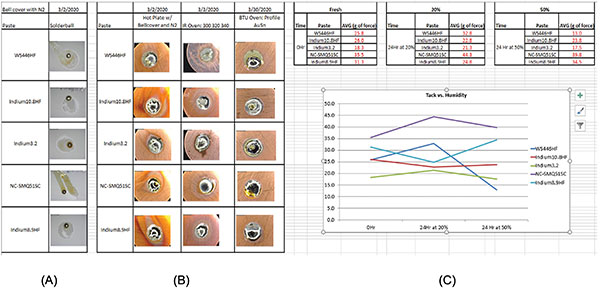
Figure 8. Flux vehicle tests for (A) solderball testing, (B) wetting testing, and (C) tack versus humidity.
Solderball testing (A):
- Each solder paste was reflowed on a hot plate with a bell cover, which was set at 325°C; each was then purged under nitrogen.
- Images were taken to compare the coalescence of each solder paste to create a ranking from best to worst.
- NC-SMQ51SC>Indium3.2>Indium8.9HF>Indium10.8HF>WS-446HF
Wetting testing (B):
- Each solder paste was reflowed in different oven conditions under nitrogen for comparison: hot plate with bell cover (left), infrared oven (center), and convection oven (right).
- Images were taken to compare the wetting performance from best to worst.
- NC-SMQ51SC>Indium3.2>Indium10.8HF>WS-446HF>Indium8.9HF
Tack versus humidity (C):
- Each AuSn solder paste was measured for tack. This measured whether the AuSn solder paste held its tackiness from fresh conditions to 24 hrs. in different humidity environments.
- WS-446HF was unstable in a higher humidity environment. Indium8.9HF was unstable in a lower humidity environment. NC-SMQ51SC, Indium3.2, and Indium10.8HF were stable for both humidity environments.
Conclusion
Flux vehicles NC-SMQ51SC (no-clean) and Indium3.2 (water-soluble) performed best for voiding percentages in a nitrogen environment, while WS446HF (water-soluble) and Indium3.2 (water-soluble) performed best in air. Additionally, NC-SMQ51SC (no-clean) and Indium3.2 (water-soluble) outperformed all others in subsequent solderball, wetting, and humidity versus tack testing.
While almost all flux vehicles tested in a nitrogen environment met market demands for a void-free solder interface of <15%, NC-SMQ51SC and Indium3.2 were determined to be the best 80Au20Sn paste offerings currently available when encompassing all the testing parameters. For the high-temperature/gold market, NC-SMQ51SC and Indium3.2 have the proven performance necessary for specific, but not limited to, use in high-power LED array applications.
While the number of data points used is not ideal to form a concrete statistical conclusion, the trend is promising and leaves open the possibility for further testing. To gain more supporting data for voiding testing, ensuring all dies are in the “cup up” position prior to placing them on the coupons will achieve a consistent number of data points. Comparison of the initial calculated voiding percentages can be performed using an automated program on a Nordson Dage x-ray to compare to the data acquired form the Yxlon x-ray. Eventually, with the ever-improving science and technology of solder materials, other flux vehicles can be selected to test for compatibility with high-power LED applications allowing for a potential expansion of the current product line. •
is a product specialist for the high-temperature business (gold and braze products) and is a technical support engineer at Indium Corp. (indium.com); jgallery@indium.com.


