CT or PCT: That is the Question!
 A plan for coordinating 2-D and 3-D x-ray and microsectioning strategies.
Last month I discussed use of “full CT” (FCT), or 3-D x-ray, for analyzing electronic components and boards. This provides a 3-D model of the sample from which “virtual x-ray microsections” can be taken at any plane within the sample for analysis. While this can give excellent information, it does take time for the quantity of 2-D x-ray images to be acquired from 360° around the sample, from which the 3-D model is produced. Furthermore, as electronic features are small, it usually requires a set of high magnification 2-D images to provide the analytical detail within the 3-D model. As I have mentioned, the geometric magnification provided by an x-ray system depends on being able to place the object/field of view (FOV) close to the x-ray tube. As the sample is rotated within the tube-detector axis for FCT, then the larger the sample, the further away the sample must be placed to prevent a collision with the tube during rotation. Although it is possible to create an FCT model by only taking images from 180° around and using careful sample placement to allow an FOV to be placed closer to the tube, detailed information is unavailable for the model because only half the potential data are taken. Looking at an individual component under full CT does permit its placement close to the x-ray tube for high-magnification images. Once that component is on a board, however, the available high magnification for full CT is likely to be lost. At this point, cutting the sample to reduce its size becomes the only realistic option to getting the required detail from the FCT model.
So, what other 3-D x-ray techniques are available for larger electronic samples? This is where partial CT (PCT) – also known as limited angle CT – can be used. PCT is available in both offline and inline x-ray systems. PCT, like FCT, requires a quantity of 2-D x-ray images to be taken 360° around the sample to produce a 3-D model. But, as FIGURE 1 shows, during image acquisition the sample is not rotated perpendicular to the tube/detector axis (as in FCT). Instead, it can remain very close to the x-ray tube. This is because the detector is moved to an angle with respect to the sample. Then, either the detector location rotates around the FOV with the sample remaining fixed, or the detector remains fixed, and the sample rotates in the horizontal plane. This way, images are acquired from all around the FOV, with no loss of available magnification. PCT can therefore be undertaken at any location in the sample, at any level of available magnification and does not require the sample to be cut.
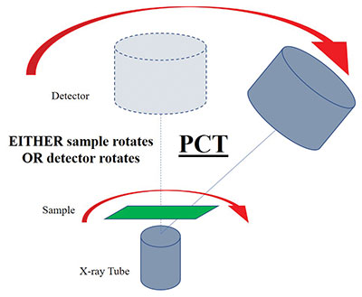
Figure 1. Schematic of how Partial CT (PCT) image acquisition works.
FIGURES 2, 3 and 4 demonstrate the capabilities of PCT. Figure 2 shows topdown 2-D x-ray images of a section of a PCB. The highlighted area has top- and bottom-side QFNs overlapping each other in the image. By making a PCT analysis, Figure 3 shows separate reconstructed 2-D slices in the z-direction (into the depth of the board) indicating, in this case, the level of voiding in the central termination of each QFN only, without any obscuration by the other device. Further analysis of the PCT slice data (Figure 4) can then provide measurement of the voiding level, which would otherwise be impossible from the top down 2-D image. In this example, only two of the many z slices from the PCT model are shown. Other slices, depending on CT model quality, could also allow investigation at different trace layers within the PCB itself.
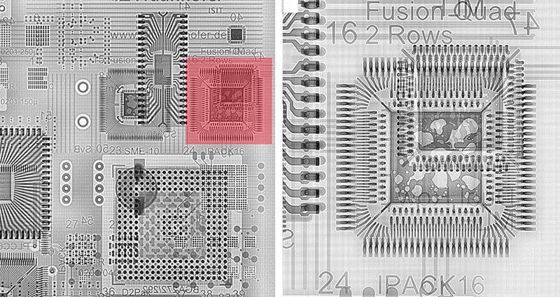
Figure 2. Top-down, 2-D x-ray image of a section of a PCB. A second, magnified x-ray image of the highlighted area is shown on the right.
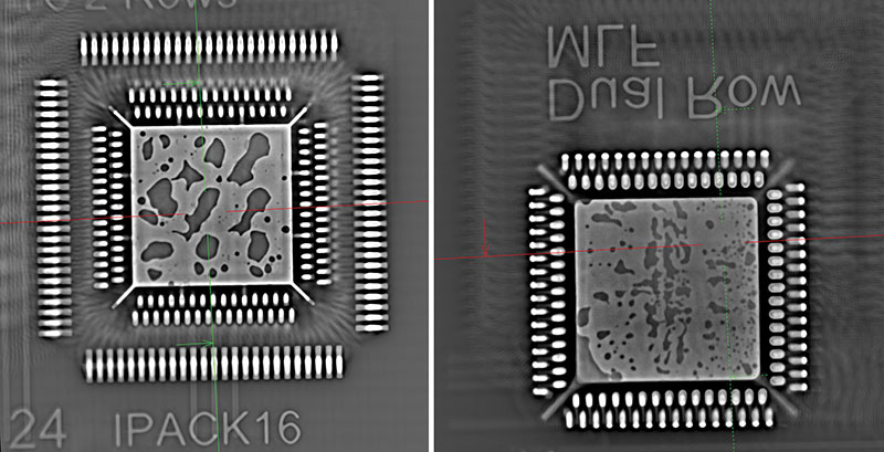
Figure 3. PCT slices at two different levels in the z-direction from the PCT model of the highlighted area in Figure 2 (from an offline x-ray system). The voiding at the main pad interface is seen for each component without being obscured by the other.
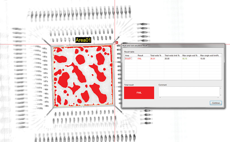
Figure 4. Calculation of the voiding level at the central pad interface slice only from the PCT data.
PCT sounds great, so why not use it instead of FCT? Sadly, the “no free lunch” rule in technology applies. They are complimentary rather than competing techniques. The limited angle of image capture means less information to put into a CT model compared to FCT. In practical terms, the PCT model is very good in the z direction (although not quite as good as FCT) but much poorer than FCT in the x and y directions of the model. Many electronics inspection needs can be met by just analyzing slices in the z direction, hence its use in inline x-ray systems. However, it should be noted that the fast sample throughput demands of inline systems typically limits image acquisition to a small number for the PCT model per FOV, which limits detail, and potentially analysis quality, compared to an offline system where more time and images can be taken. Ultimately, decide during the time/detail tradeoff if the results are good enough to see the problem and diagnose the root cause.
In conclusion, PCT offers a route to non-sample-cutting, high-magnification 3-D analysis for investigating the z direction of an object. However, like FCT, it needs a quantity of images to be taken, and that has implications for balancing the time to accomplish the technique against the eventual quality of model it produces and the analytical results that can be obtained. The poor data PCT provides in the x and y model directions, compared to FCT, may offer limited, if any, additional analytical data. Yet, the PCT model does give rise to “characteristic shapes” from the reconstruction in these planes, albeit very different to full CT, and this may offer opportunities for some analysis in the future. Consider PCT as on the path of analysis techniques that you use: 2-D x-ray, followed by PCT, followed by FCT, followed by microsectioning. At what point and time in this sequence do you find the answer to your issue and are you able to do this without cutting up the board? With great apologies to The Bard, should you consider whether ‘tis nobler in the mind to suffer the slings and arrows of poor joint quality or to take arms against a sea of troubles by using a variety of available x-ray and other techniques? The answer to the question then becomes, you may need CT and PCT! CA
Au.: Images courtesy Peter Koch, Yxlon International.
, is an expert in use and analysis of 2D and 3D (CT) x-ray inspection techniques for electronics; dbc@bernard.abel.co.uk.


