Solder Fillet Tearing

SAC solders are susceptible to the process indicator, but IPC-A-610F permits it.
Solder fillet tearing is another process phenomenon seen with SnAgCu (SAC) alloys. It is not typically seen on AgCu, but more commonly seen on higher-silver SAC. During these trials, tearing was seen on the surface of robotic laser and iron-soldered joints but did not appear to increase in size after static ageing or during temperature cycling. Tearing is highlighted in IPC -A-610F, Acceptability of Electronic Assemblies, for lead-free materials only. It is considered acceptable for Class 1, 2 and 3.
The two microsection images (FIGURE 1) show the tearing of the solder between the grain boundaries on the surface of the joints. The optical image (FIGURE 2) shows the surface of one joint, with the tearing visible in the solder surface.
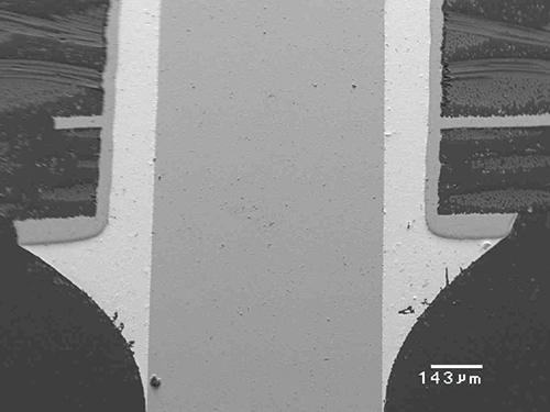
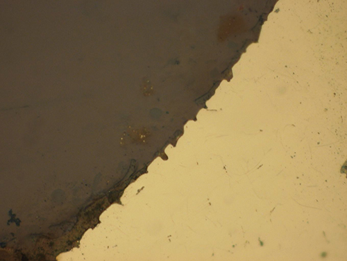
Figure 1. Microsections of solder tear between grain boundaries.
Figure 2. Solder joint surface showing tearing of solder after soldering iron application.
These are typical defects shown in the National Physical Laboratory’s interactive assembly and soldering defects database. The database (http://defectsdatabase.npl.co.uk), available to all this publication’s readers, allows engineers to search and view countless defects and solutions, or to submit defects online. To complement the defect of the month, NPL features the Defect Video of the Month, presented online by Bob Willis. This describes over 20 different failure modes, many with video examples of the defect occurring in real time.
is a consultant at the National Physical Laboratory (npl.co.uk); martin.wickham@npl.co.uk. His column appears monthly.


