

Peeling Back Graping

Exhausted flux can cause incomplete reflow.
Here is a close-up optical image of a small area array package placed on a solder paste deposit. The PCB has a gold surface finish. It is good process control practice to check parts periodically. If viewed after placement, we would say the part has been correctly placed in relation to the pad; however, we may highlight a paste alignment issue or paste displacement to be investigated.
This example was found after reflow when the rest of the assembly had reflowed perfectly. There are two main reasons for seeing this type of defect. First, and most obvious, is the reflow profile was incorrect: the rest of the board reflowed correctly as it reached temperature and was maintained for enough time to permit joints to reflow. These joints did not reflow, however. The proper response would be to check the profile with thermocouples mounted under and to the side of the area array device. It’s surprising that many companies do not pay attention to the process fundamentals.
The second possibility is the reflow profile was still incorrect for the paste. In some cases, high-mass component termination and the paste deposit spend too long at elevated temperature just below paste reflow. When the paste and these joints do move to reflow temperature, the flux medium in the paste is partly or fully exhausted. This is basically the same as what industry calls “graping,” or incomplete reflow and coalescence of the solder paste particles.
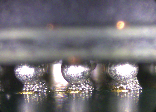
Figure 1. Improper reflow profile can cause the paste to partially coalesce, which in turns looks like a cluster of grapes.
These are typical defects shown in the National Physical Laboratory’s interactive assembly and soldering defects database. The database (http://defectsdatabase.npl.co.uk), available to all this publication’s readers, allows engineers to search and view countless defects and solutions, or to submit defects online. To complement the defect of the month, NPL features the “Defect Video of the Month,” presented online by Bob Willis. This describes over 20 different failure modes, many with video examples of the defect occurring in real time.
is with the National Physical Laboratory Industry and Innovation division (npl.co.uk); chris.hunt@npl.co.uk. His column appears monthly.


Press Releases
- Altus Group Invests in Major Headquarters Expansion to Showcase Complete Turnkey Manufacturing Capability
- ViTrox Americas Welcomes Eric Cruz as Technical Support Engineer
- ECD Strengthens Engineering Team with New Software Development Hire
- ViTrox Americas Welcomes Doug Ennis as Senior Field Applications & Service Engineer